
Estimated Study Time: 31 minutes
The purpose of earthing
System earthing involves the provision of a connection to the general mass of earth. This connection should have a resistance not greater than that required to operate safety mechanisms to isolate the electricity supply from a fault situation.
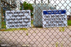
 Measurements and Calculations Of Earth Electrode Systems (According to BS 7430) - photo credit: dmcpower.com
Second important characteristic of earthing connection is that it MUST be capable of carrying the maximum expected fault current.
The value of resistance required might not always be amenable to an automatically set value. Therefore, the various factors which affect the resistance to earth and fault current capacity of the buried conductor, designated the earth electrode, should be considered.
This should include the size and shape of the earth conductor, the resistivity of the soil in which it is buried and the connection of the system to it. It is also essential to consider the current density at the surface of the earth electrode and the ground potentials in its vicinity.
- Nature of site
- Soil resistivity
- Measurement of soil resistivity
- Types of earth electrodes and their resistance calculation
1. Nature of site
The basic nature and properties of soil in a given location cannot be changed without considerable expense, and careful consideration of the geology should be used to determine the best location for an earthing system.
Where there is an option, a site should be chosen in one of the following types of situations in the order of preference given:
- Wet marshy ground;
- Clay, loamy soil, arable land, clayey soil, clayey soil or loam mixed with small quantities of sand;
- Clay and loam mixed with varying proportions of sand, gravel, and stones;
- Damp and wet sand, peat.
Care should be taken to avoid a site where water flows over it (e.g. the bed of a stream) for the beneficial salts can be entirely removed from the soil in such situations.
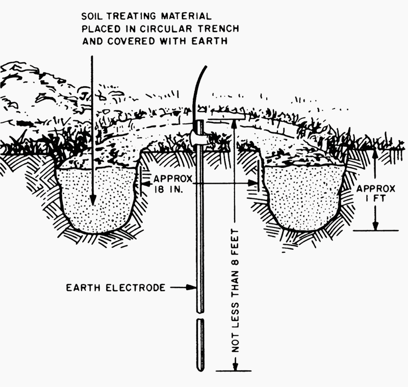
1.1 Soil treatment
In high resistivity locations or on rocky ground where long term performance is required, it may be considered necessary to utilize a conductive concrete to improve earth contact resistance around an earth rod or strip (tape) where applicable.
There are commercially available materials to achieve this effectively, but care should be taken to understand how they work during installation to ensure that they remain in contact with the rod or strip and do not shrink or swell away after drying out.
Chemical treatment of soil has environmental implications and should not be considered as a long term solution in order to meet a specified level of resistance, apart from the risk of corrosion to the earthling system. Coke breeze should also not be used due to its highly corrosive nature.
2. Soil resistivity
The resistance to earth of a given electrode depends upon the electrical resistivity of the soil. Most first approximation formulae are related to homogenous soil, which is rarely the case in practice, where the different layers of strata will affect the distribution of current passing through the electrode.
Table 1 gives examples of resistivity only. These figures are very general and should not be used to replace actual measurements made at the proposed site. They may be used to give an indication of the difficulties that one might face in preparing an adequate design at the chosen location.
Soil temperature has some effect on the upper layers of strata, but is only important under frosty conditions. Therefore any part of an electrode system which is less that 0.5 m below ground level should not be considered to be effective.
Table 1 – Examples of soil resistivity in Ωm

NOTE! – Table 1 is only to be taken as a general guide. Earth resistivity is essentially electrolytic and affected by the moisture content and the soil’s ability to retain moisture plus the chemical composition and concentration of beneficial salts dissolved in the water.
Columns 2 and 3 relate to most of the British Isles, but column 5 is more specific to marshy flats around river estuaries.
3. Measurement of soil resistivity
Soil resistivity may be measured in a similar manner to the establishment of the resistance of the earth electrode.
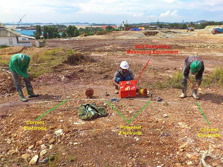
Measurements of the soil resistivity for the pre-determination of the resistance to earth or the impedance to earth should be carried out using a four probe method (widely known as the Wenner method) as follows.
- Drive four equally spaced test electrodes to a depth of not greater 5% of their spacing apart a. It is important to ensure that their resistance areas do not overlap (Figure 2)
- Pass current between the two outer electrodes
- Measure the earth potential between the two inner electrodes
The resistance R should be taken as the ratio of the voltage between the inner electrodes and the current between the outer electrodes. In homogenous soil the average resistivity ρ in ohm metres (Ωm) may be taken as:
ρ = 2 π a R
where:
- a is the spacing between electrodes, in metres (m);
- R is the resistance measured between the middle electrodes, in ohms (Ω).

The resistivity so determined applies to an electrode separation distance a, which is related to the depth of investigation. By repeating the measurement with increasing values of a, the apparent resistivity involving greater depths may be assessed.
This may be taken as an indication of the possible gain from driving deeper rods, etc., into strata of a lower resistivity to get the required resistance.
Few more words on Wenner method…
Four equally spaced test spikes should be driven to a depth of up to 1 m, the depth not exceeding 5% of their separation a.
It is important to ensure that their resistance areas do not overlap. Current should be passed between the two outer electrodes and the resistance R may be found as the ratio of the voltage between the inside electrodes to the current conducted through the outside electrodes.
EXAMPLE – If the distance a between electrodes is 1 m the constant for the test setup is calculated as (2 × 3.14 × 100) cm = 628 cm. If the instrument reads 40 Ω the earth resistivity is (40 × 628) Ωcm = 25 120 Ωcm.
It should be noted that environmental conditions such as temperature have an impact on earth resistivity with a corresponding decrease in resistivity as temperature rises.
4. Types of earth electrodes and their resistance calculation
An earthing system should be of the highest integrity and of robust construction to ensure that it remains safe and will not endanger the health and safety of persons or their surroundings. The majority of the formulae presented in this section relate to low frequency currents and high frequency examples are not included.
It is therefore important to recognize this issue if a long horizontal tape or bare cable is being considered for producing a low earth resistance, even though the impedance will ultimately be limited to a final value (see Figure 4).
Earthing systems should consist of copper conductors, copper clad or austenitic steel rods of appropriate dimensions, cast iron plates, or steel piles used individually or connected together in combination to form a single local earth electrode system.

The formulae which follow are all based on homogeneous soil conditions, so in most practical situations only give a reasonable idea of the problems (within 15% accuracy) that might exist if the strata is such that the resistivity changes at different levels.
However, onsite resistivity testing should always be carried out prior to carrying out an earth system design and installation.
The effect of shape on an electrode resistance is related to the current density around the particular electrode considered. To obtain a low overall resistance the current density should be as low as possible in the medium surrounding the electrode.
This may be achieved by making the dimensions in one direction large by comparison to the other two. Thus a pipe rod or strip has a much lower resistance than a plate of equal surface area.
a) Plates
The approximate resistance to earth of a plate R in ohms (Ω) may be calculated from:

where:
- ρ is the resistivity of the soil (assumed uniform), in ohm metres (Ωm);
- A is the area of one face of the plate, in square metres (m2).
Plates, if used, should be installed as small units of not greater than 1.2 m × 1.2 m connected in parallel vertically and at least 2 m apart. The minimum ground cover should not be less than 600 mm and ideally the surrounding soil should be damp.
Where the plate is placed in a cut out slot, e.g. in a chalk bed near the surface, the slot should be big enough to allow at least 300 mm thickness of soil or other conducting low resistivity medium cover around the whole plate. This requires careful assembly during installation to ensure that the bottom of the plate is resting in the medium used and not on the chalk or high resistivity substrata.
NOTE! For conventional sizes, the resistance is approximately inversely proportional to the linear dimensions, not to the surface area, i.e. a 0.9 m × 0.9 m plate has a resistance approximately 25% higher than a 1.2 m × 1.2 m plate.
b) Rod electrode
The resistance of a rod Rr in ohms (Ω) may be calculated from:

where:
- ρ is the resistivity of soil, in ohm metres (Ωm);
- L is the length of the electrode, in metres (m);
- d is the diameter of the rod, in metres (m).
NOTE! – Change of diameter has little effect on the overall value of resistance, and the size is more governed by the mechanical strength of the rod to withstand being mechanically driven when deep earth rods are required e.g. to depths of 20 m or more.
c) Parallel connection of aligned rods
The resistance Rt in ohms (Ω) of n vertically driven rods set s metres apart may be calculated from:
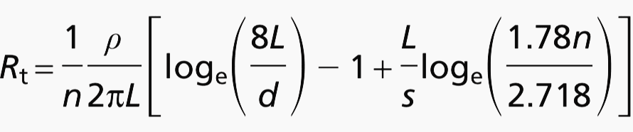
where:
- ρ is the resistivity of soil, in ohm metres (Ωm);
- L is the length of the electrode, in metres (m);
- n is the number of rods;
- s is the spacing between the rods, in metres (m).
NOTE! – This is based on work carried by Heppe R.J. in 1998 dealing with the computational approach to the potential at the surface face of rods, etc. and gives a slightly more optimistic answer than might be expected.
This is related to the hemispherical radius of the rod and that has avoided the effects of using less than the two-times constraint in design thinking. This affects the interference characteristics of multiple rod/tape, etc. systems when the spacing is reduced below the two-times value.
d) Strip or round conductor electrodes
This section deals only with a straight run of conductor. Other shapes are not covered here.The resistance Rta in ohms (Ω) of a strip or round conductor may be calculated from:
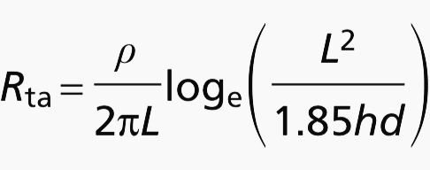
where:
- ρ is the resistivity of soil, in ohm metres (Ωm);
- L is the length of the electrode, in metres (m);
- h is the depth of the electrode, in metres (m);
- d is the diameter of the round conductor or diameter of the equivalent cross sectional area of the strip, in metres (m).
When two or more strips in straight lengths, each of length L in meters (m) and a separation distance s metres are laid parallel to each other and connected together at one end only the combined resistance may be calculated from the following equation:
Rn = F R1
where:
- Rn is the resistance of n conductors in parallel, in ohms (Ω)
- R1 is the resistance of a single strip of length L, calculated from the preceding Rta equation, in ohms (Ω).
- F has the following value:
- For two lengths: F = 0.5 + [0.078(s/L)] − 0.307
- For three lengths: F = 0.33 + [0.071(s/L)] − 0.408
- For four lengths: F = 0.25 + [0.067(s/L)] − 0.451
- Provided that 0.02 < (s/L) < 0.3
e) Mesh
The resistance of a mesh (grid) Rm ohms (Ω) may be calculated from:
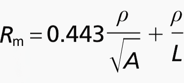
Where:
- ρ is the resistivity of soil, in ohm metres (Ωm);
- A is the actual area covered by the mesh, in square metres (m2);
- L is the total length of strip used in the mesh, in metres (m).
f) Resistance of an electrode encased in low resistivity material, e.g. conducting concrete
The resistance of a backfilled electrode Rb in ohms (Ω) may be calculated from:
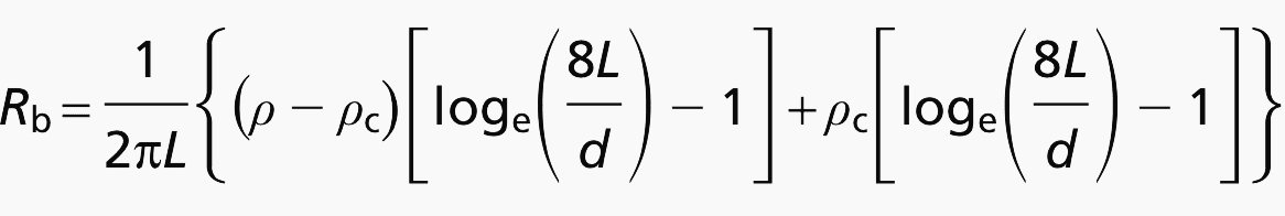
where:
- ρ is the resistivity of soil, in ohm metres (Ωm);
- ρc is the resistivity of the conducting material used for the backfill, in ohm metres (Ωm);
- L is the length of rod, in metres (m);
- d is the diameter of the rod, in metres (m).
g) Miscellaneous electrodes
There are many configurations that can be set out under this heading, but a few of those which one is most likely to try first in order to achieve the required value are included especially when dealing with deep reinforced piles, etc.
- Three rods at the vertices of an equilateral triangle
- Two strips set at right angles to each other meeting at one corner
- Three strips set at 120° meeting at the star point all of equal length
- Four strips set in a cruciform
- Structural steelwork
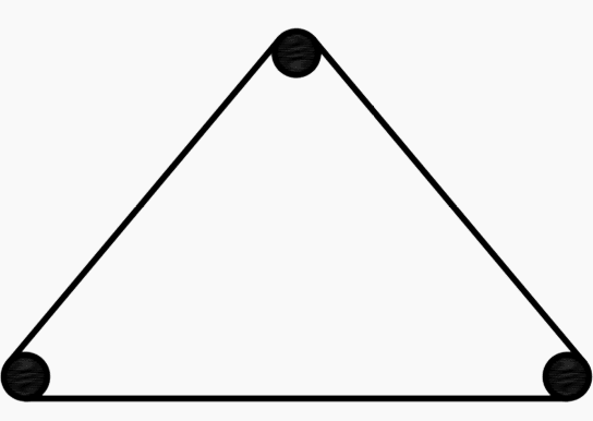
Three rods at the vertices of an equilateral triangle
The resistance Re in ohms (Ω) of three interconnected rods set out at the vertices of an equilateral triangle (see Figure 5) of side s metres length may be calculated from:

where:
- ρ is the resistivity of soil, in ohm metres (Ωm);
- L is the length of rod, in metres (m);
- d is the diameter of rod, in metres (m);
- s is the length of one side of the equilateral triangle, in metres (m).
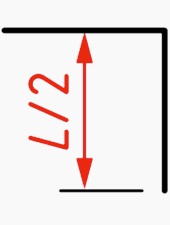
Two strips set at right angles to each other meeting at one corner
The resistance RL in ohms (Ω) of two strips of equal length set at 90° with one corner touching (see Figure 6) may be calculated from:
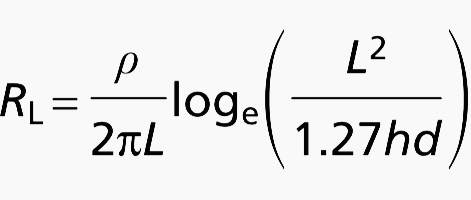
where:
- ρ is the resistivity of soil, in ohm metres (Ωm);
- L is the total length of strip in metres (m);
- h is the depth of burial in metres (m);
- d is the diameter of the round conductor or diameter of the equivalent cross sectional area of the strip in metres (m).
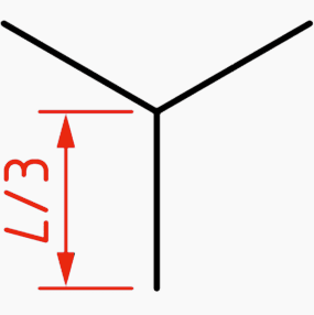
Three strips set at 120° meeting at the star point all of equal length
The resistance RS in ohms (Ω) of a star arranged strip (see Figure 7) may be calculated from:
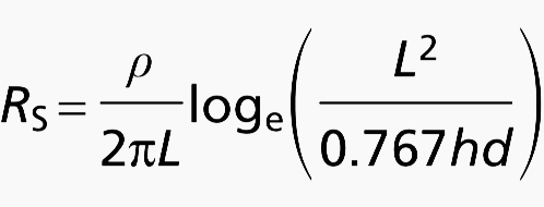
where:
- ρ is the resistivity of soil, in ohm metres (Ωm); is the total length of strip in metres (m);
- L is the depth of burial in metres (m);
- h is the diameter of the round conductor or diameter of the equivalent cross sectional area of the strip in metres (m).
Four strips set in a cruciform
The resistance Rcr in ohms (Ω) of four strips set out in a cruciform (see Figure 8) may be calculated from:
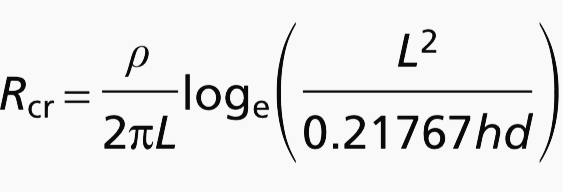
- ρ is the resistivity of soil, in ohm metres (Ωm);
- L is the total length of strip in metres (m);
- h is the depth of burial in metres (m);
- d is the diameter of the round conductor or diameter of the equivalent cross sectional area of the strip in metres (m).
Structural steelwork
Foundation metalwork in concrete may be used as a ready made and effective earth electrode. The total electrode area formed by the underground metalwork of large structure may often be used to provide an earth resistance lower then that obtainable by other methods.
Overall values well below 1 Ω are obtainable.
It is important that consideration is given to the possibility of corrosion of the metalwork reinforcement. The products of corrosion occupy a greater volume than the original metal and cracking might occur. In particular, continuous earth currents should be given attention.
NOTE! – It might be necessary to consider the need for cathodic protection.
Alternating current should not be expected to cause corrosion, but, rectification sufficient to produce a very small proportion of direct current might take place.
Wherever significant continuous earth leakage current is expected, it is recommended that a main electrode of the types described in previous section be provided to which the foundation electrodes can be bonded to provide auxiliary electrodes, thus giving assistance to high fault currents.
Corrosion of concrete encased steelwork, subject to a.c. fault currents within its carrying capability, may be assumed to be negligible.
NOTE! – Damage to the concrete in the form of cracking, due to arcing or the rapid evaporation of moisture, can occur where the long-term duration earth fault currents exceed the carrying capability of the electrode. This situation is unlikely to arise if the electrode has a resistance sufficiently low to avoid dangerous voltages to earth.
Concrete is hygroscopic and, except in dry locations, when buried in soil, it may be expected to have a resistivity of about 30 Ωm to 90 Ωm, at normal temperatures. This is lower than some types of soil.
It is essential to measure the resistance to earth of any metalwork it is intended to use as an electrode, and to monitor its value at regular intervals afterwards, in order to confirm that it continues to provide an adequate connection to earth.

Ideally confirmation of the combined resistance of all the electrodes should be obtained, but the earth resistance of a structure covering a large area might be quite low and an accurate measurement on a completed structure might be difficult or impossible to achieve.
If possible, it is advantageous and recommended to measure the resistance of several such footings to gain an indication of the likely variation of resistance.
On the assumption that a representative value of footing resistance can be obtained, the combined effect of all similar footings RTOT in ohms (Ω), assumed to be arranged in an approximately rectangular plan, may be determined from the following:

Where:
- R1 is the resistance of one footing, in ohms (Ω);
- λ is the factor from Table 2;
- ρ is the resistivity of soil, in ohm metres (Ωm);
- s is the spacing of footings, in metres (m);
- n is the number of footings used as electrodes (see the note to Table 2).
NOTE! – This equation is based on assumption that the spacing between adjacent electrodes is such that the ratio ρ/2πR1s is less than approximately 0.2.
Table 2 – Factors for vertical electrodes arranged in a hollow square

NOTE! – The large proportion of the resistance is due to the concrete to earth is immediately around the metalwork and is dependent on its moisture content. After construction and with the passage of time this moisture content will approach equilibrium with that of the soil, and will usually be dryer than when first laid.
Allowance should be made for the consequent increase in electrode resistance due to changes in moisture content when using measurements made during the installation of a structure.
In the case of contacts between metalwork within concrete or below ground, such as reinforcing bars, this may best be effected by welding. Above ground and at anchor bolts it may generally done by attaching a bond conductor to bypass each structural joint. This applies particularly to surfaces which might have been primed before assembly.
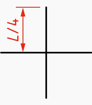
The resistance to earth of a reinforced concrete foundation Rr in ohms (Ω) may be estimated by assuming that only the vertical reinforcing rods are bonded to the building structure or to the earthing system. The effect of other reinforcement which might be attached by wire ties only, may be neglected.
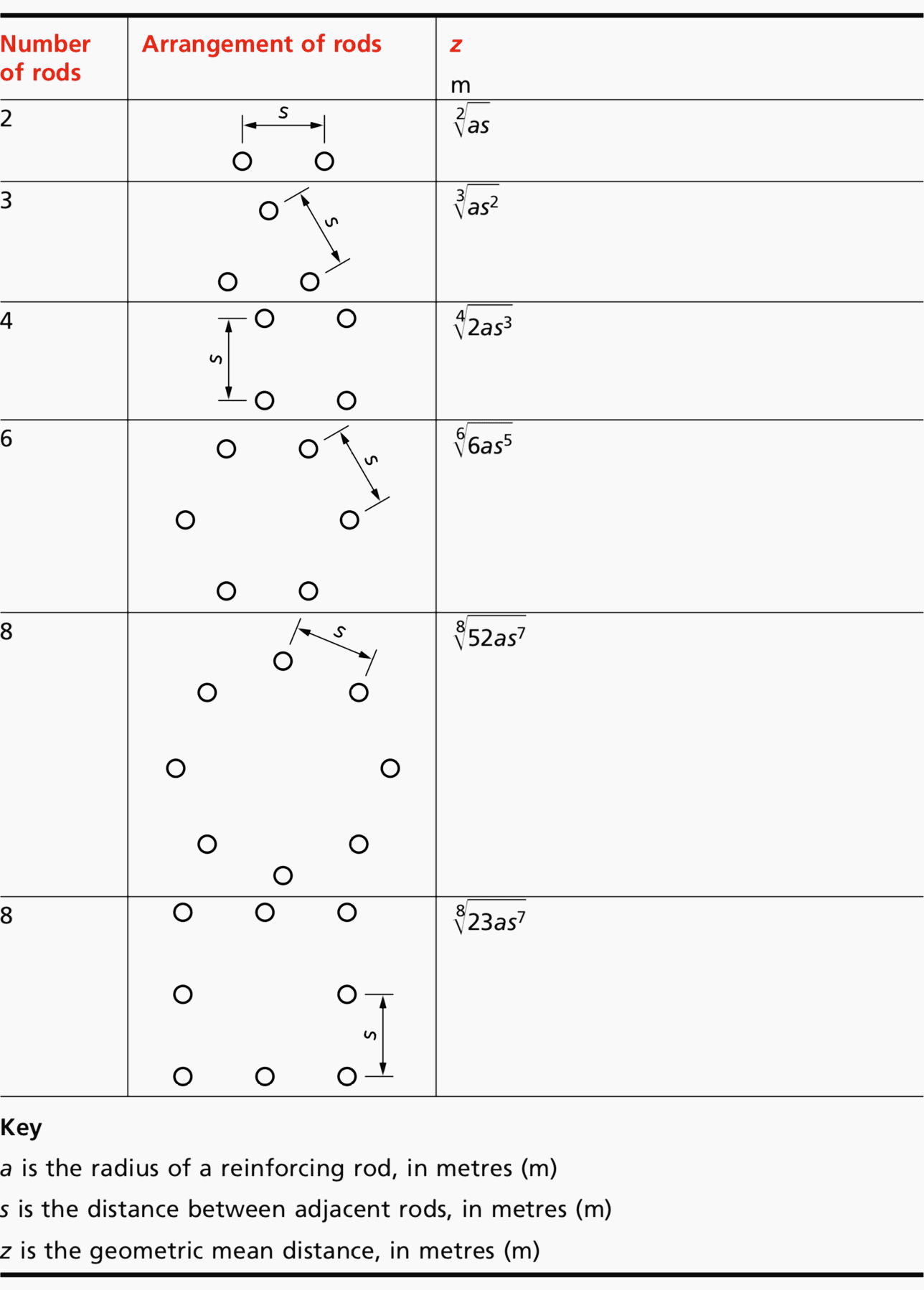
It may be assumed that the rods are equally spaced in a symmetrical pattern
(see Table 3).
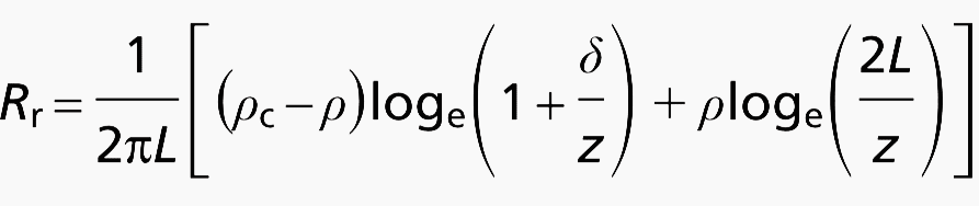
where:
- ρ is the resistivity of soil, in ohm metres (Ωm);
- ρc is the resistivity of concrete, in ohm metres (Ωm);
- L is the length of reinforcing rod below ground level, in metres (m);
- δ is the thickness of concrete between rods and soil, in metres (m);
- z is the geometric mean distance of rod cluster, in metres (m).
Reference // BS 7430:2011 – Code of practice for protective earthing of electrical installations
Related electrical guides & articles


Edvard Csanyi
Hi, I'm an electrical engineer, programmer and founder of EEP - Electrical Engineering Portal. I worked twelve years at Schneider Electric in the position of technical support for low- and medium-voltage projects and the design of busbar trunking systems.I'm highly specialized in the design of LV/MV switchgear and low-voltage, high-power busbar trunking (<6300A) in substations, commercial buildings and industry facilities. I'm also a professional in AutoCAD programming.
Profile: Edvard Csanyi

Thank you for your information.
Please check the formula of “Three rods at the vertices of an equilateral triangle” with BS 7430:2011+A1:2015, part 9.5.8.1, Page 41 !
Best regards
In f) the resistance of electrode encased in backfilling compound the formulas yields the same value for different values of resistivity for backfilling compound pc, Term pc is gets cancelled out each time, so need to check or modify the formula. Kindly suggest if any modification.
regarding the formula of the hollow square the letter n is representing the number of rods for one side of the square but the resistance is for the total resistance so Is this resistance for one side only or its for the 4 sides?
Hello,
Can the formula for vertical electrodes arranged in hollow square be used for electrodes arranged in L shape or T shape?
Thank you.
Could the plate equation for resistance be used for small holidays on an underground pipeline, say 0.01cm*cm?
Particularly, I’m interested if there would be a way to calculate a pipeline’s resistance based on an expectation of holiday defects in an insulating coating.
we have substation earthing network connected with grid in parallel, the size of the earth rod is 16mm dia , but as per specification it should be 20mm , we have 64 nos of rod connected of size 16mm , which formula can used to increase the size of rod to20mm to overcome the issue .
for any kind of electrode there is a formula. however, there are different kinds of materials like iron, steel, or copper. is there any kind of special formula for each of them?
I would be thankful if you send the response to my Email.
kindly provide how we can define rod specification on available value of soil resistivity?
I have system for gen. Consist of one earth pit only
The reading of separate earth pit is 1.8 ohm and the reading of the system is .85 ohm as I connect the cable from earth rod to earth bar .
So how the reading become less as the equation Rt= R for earth rod + R for cable and the connection is series
where is soil resistance in the calculation of Three rods at the vertices of an equilateral triangle formula?
Could you please highlight regarding horizontal earth rods 🙏?
well done sir, may i ask how to break down your formula from resistance of the material to the resistance of the plates shape.. In my place, grounding electrode had a rectangle shape, i just want to know what is the best formula to calculate it
I am faced with a peculiar issue. 2 nos earth electrodes that are more than 80 ft apart in a alluvial & lighter clays, marls & porous limestones soil having very low resistivity are found electrically conductive, while they are required to be electrically independent.
What is the method to make them electrically non conductive with each other.
Hey ,
which standard mention earthing resistance required less than 1 ohms ?
Dear Sir,
Please refer IEEE Standard 80, page 64.
Valuable information
thanks for this information
I have a question:
where is soil resistance in the calculation of Three rods at the vertices of an equilateral triangle formula?
This is one of the best design reference i have seen.
Very practical information
it is useful. Thanks
Excelente informação.
Valuable information
it is valuable information.
thank you