Methods of neutral earthing
The mode of operation of an MV industrial power system that is galvanically isolated from the public power supply is determined by the method of neutral earthing on the secondary side of the transfer transformer.
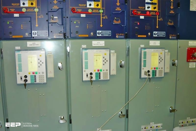
The following methods of neutral earthing can be used to earth secondary-side neutral points of transfer transformers:
- Isolated neutral,
- Earth-fault compensation or resonant neutral earthing,
- Low-impedance neutral earthing.
Power systems with low-impedance neutral earthing also include those with isolated neutral or with resonant neutral earthing whose neutral point is earthed temporarily on each occurrence of an earth fault.
Solid neutral earthing, which is not mentioned, is not particulary important in MV industrial power systems due to of the high line-to-earth short-circuit currents and the resulting interference (EMC), earthing (permissible touch voltage) and dimensioning problems (required rated short-time withstand current of the cable screen).
Power system with isolated neutral
A power sytem with isolated neutral (Figure 1) is defined as a power system in which the neutral points of transformers and generators are either not connected to earth or only connected to earth through measurement and protective devices with a very high impedance or through an overvoltage protector.
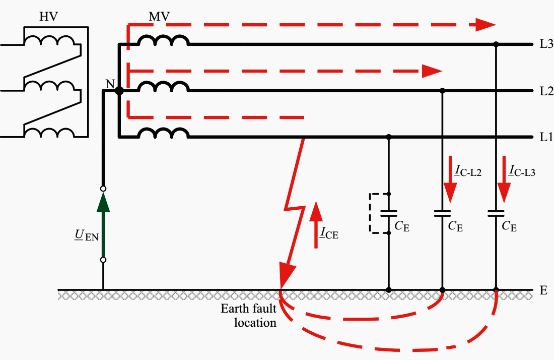

Fault current: IF = ICE = j × 3 × ω × CE × ULE ; ICE ≤ 30 A
Where:
- CE – Line-to-earth capacitance
- ICE – Capacitive earth-fault current
- ULE – Line-to-earth voltage (ULE = ULL / √3)
- UEN – Neutral-point displacement voltage
- ω – Angular frequency (2 × π × ƒ)
Operation with isolated neutral is the simplest form of earth-fault-oriented neutral-point connection. In the event of an earth fault, voltage displacement to earth occurs.
The line-to-line voltages of the earth-faulted power system, on the other hand, do not change. Because of this, no reaction arises that is disadvantageous for the loads connected to the power system and operation can be maintained even in the event of an earth fault.
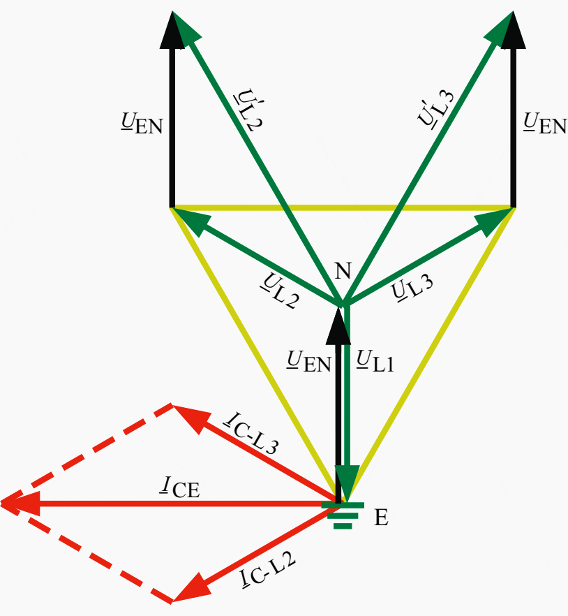

Where:
- UL1, UL2, UL3 – Star voltage of lines L1, L2, L3
- UL2, UL3 – Star voltage on the faultless phases L2 and L3 raised by the factor √3
(power-frequency overvoltage) - UEN or Uen – Neutral-point displacement voltage
- IC-L2 or IC-L3 – Capacitive charging current of line L2 or L3
- ICE – Capacitive earth-fault current at the fault location
However, the voltage displacement to earth causes the capacitive earth-fault current ICE of the entire power system to flow through the earth fault location. This earth-fault current, which is largely determined by the earth capacitance of the lines CE, has the magnitude ICE ≈ 3 × ω × CE × ULE.
Due to the comparatively low thermal stress at ICE < 30 A, the earth-fault arc can burn for longer without destroying the insulation of the intact conductors. Destruction of this insulation would entail a serious danger of the earth fault developing into a double earth fault or short circuit.
To detect the earth-fault location, SIPROTEC relays with sensitive earth-fault detection can be used. They measure the capacitive residual currents. The residual currents of the faultless and earth-faulted feeder differ in their magnitude and direction (Figure 3).
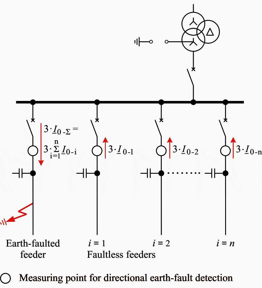

In faultless feeders, all residual currents flow in the same direction. Their magnitude depends on the magnitude of the relevant capacitive charging current. The residual current of the earth-faulted feeder is the sum of the charging currents of all faultless feeders flowing in the opposite direction.
By means of the measurement with reference to the neutral-point displacement voltage Uen of this capacitive residual current (sinφ measurement), the SIPROTEC relay detects the feeder with the earth fault.
The neutral-point displacement voltage Uen required for earth-fault direction detection is obtained by connecting single-pole-earthed inductive voltage transformers (Figure 4).
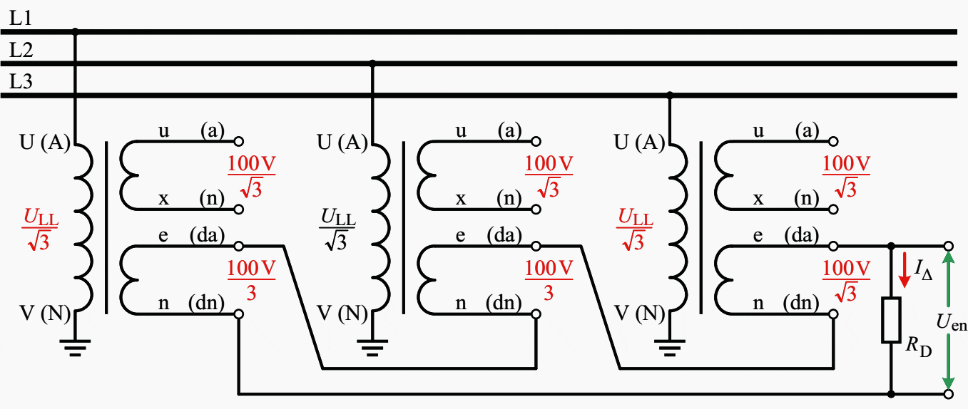

If this is used in a system with isolated neutral, there is a risk of relaxation oscillations (ferroresonance). Relaxation oscillations are caused by interaction of the non-linear no-load inductance of the voltage transformers connected to earth with the earth capacitance of the network.
The relaxation oscillations, which mainly occur when an earth fault arc is extinguished or on an energizing operation, put the iron core in the saturated state and cause high core losses.
As a consequence of these high core losses, the voltage transformer can be thermally overloaded and finally destroyed.
The simplest and safest way of avoiding relaxation oscillations is to insert an ohmic damping resistor RD into the earth-fault windings of the three voltage transformer units interconnected in an open delta (Figure 4). The damping resistor RD is rated so that neither it nor the voltage transformer is thermally overloaded.
Table 1 contains standard values for damping resistors that have proven convenient in practice.
Table 1 – Standard values for damping resistors RD
| e-n or da-dn winding of the voltage transformer | Damping resistor RD | |
| Rated thermal limiting output Sr sec | Rated long-duration current IΔ | |
| 75 W | 4 A | 25 Ω / 500 W |
| 100 W | 6 A | 25 Ω / 500 W |
| 150 W | 8 A | 12.5 Ω / 1000 W |
The choice of RD is based on the thermal limiting output (rated long-duration current) of the e-n or da-dn winding of the voltage transformer. If these standard values cannot be used, other values can be calculated.
The calculation must be performed as follows (Equations 1, 2, 3 and 4):
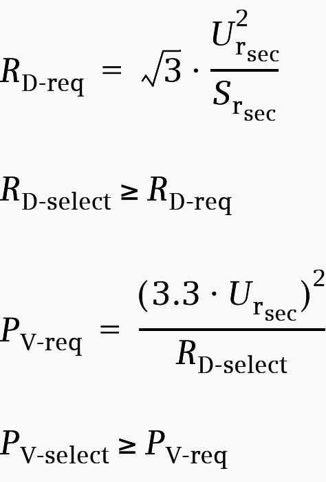

Where:
- RD-req required damping resistor (minimum value)
- RD-select selected damping resistor
- PV-req required thermal load capacity (minimum value)
- PV-select selected thermal load capacity
- Ursec secondary rated voltage of the earth-fault winding
- Srsec thermal rated limiting output
Example
Example of calculation of the damping resistor dimensioning according to above formulas (RD-req and PV-req): see Table 2 below.


Table 2 – Calculation of the damping resistor dimensioning
| Rated secondary voltage of the residual voltage winding | Ursec = 100 V / 3 |
| Rated thermal limiting output | Srsec = 30 VA |
| Required damping resistor acc. to Eq. 1 | RD-req = 64.2 Ω |
| Selected damping resistor | RD-select = 65 Ω |
| Required thermal load rating acc. to Eq. 3 | PV-req = 186.2 W |
| Selected thermal load rating | PV-select = 200 W |
A further negative phenomenon in isolated-neutral systems are overvoltage levels that result in an excessive voltage stress on the equipment insulation.
On occurrence of an earth fault, the capacitive charge reversal of the faultless lines is brought about by a transient. This transient occurs as a medium-frequency oscillation that briefly causes an overvoltage. The transient overvoltage on occurrence of an earth fault can be 3 to 3.5 times the star voltage.
This transient overvoltage is brought under control by the insulation level that is standardized and assigned to the specific rated voltage of the item of equipment (Table 3).
Table 3 – Standardized insulation levels in the range 1 kV < Um ≤ 36 kV according to DIN EN 60071-1 or IEC 60071-1
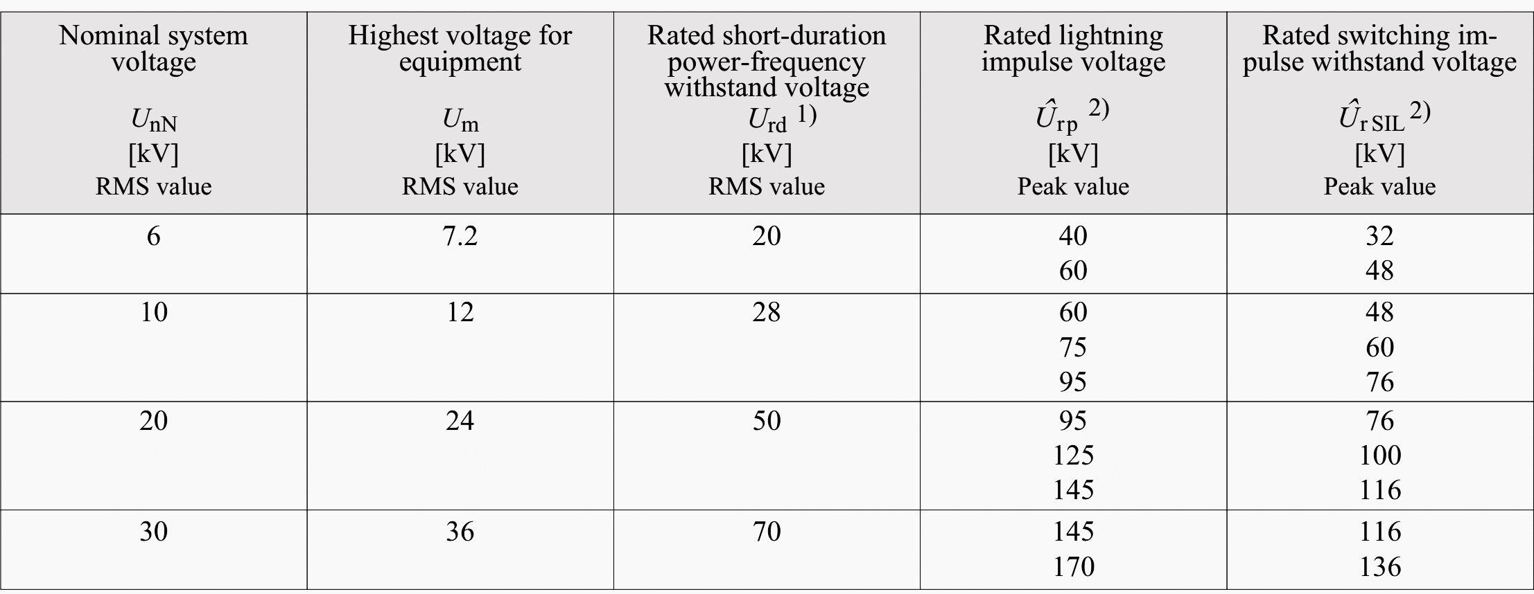

- Alternating voltage with a frequency between 48 Hz and 62 Hz and a duration of 60 sec.
- Voltage pulse with a rise time of 1.2 μsec and a time to half-value of 50μsec
- For the MV range 1kV < Um ≤ 36 kV, no rated switching impulse level is defined in a standard. It is considered in the insulation coordination with a absolute value of 0.8×Urp . Because of the longer time to half-value of the transient switching overvoltage, UrSIL is less than Urp.
Compliance with these time limits must be ensured in the operation of cable networks with isolated neutral.
Despite its negative side-effects (ferroresonance, high transient and long-lasting power-frequency overvoltages), operation with isolated neutral is very important for industrial power supplies. This method of neutral earthing is preferred in small cable networks and those without (n–1) redundancy.
Source: Planning Guide for Power Distribution Plants by Dr.-Ing. Hartmut Kiank and Dipl.-Ing. Wolfgang Fruth (Siemens)









Great, in this case, does the line to line capacitance effect or not ???
My problem is: As a downstream MCC operator, when the power supply (from the service supplier) grounded at one phase, Is that possible I can find it without cutting off the whole power and show the evidence to the supplier.
I got good reviews
Hi Guys just Google this – Planning Guide for Power Distribution Plants by Dr.-Ing
and you can have Siemens PDF file for free…happy days
I would like to know Earthing System for Star – Delta Transformers which are using on Marine Vessels.
Please give me the the real applying drawing, not only theory.
Sir,I want to learn design for electrical so please help me
I like your blogs,it is very good knowledge.Requesting to you send the blogs in pdf format so it is easy to download
merci pour ces riche information