


Estimated Study Time: 32 minutes
Earthed and Unearthed Cables
Differences and Applications
The selection between earthed and unearthed cables is not merely a material choice, but a fundamental system design parameter dictated by the network’s grounding topology. This distinction directly governs capital expenditure, ongoing operational reliability, and the physical characteristics of the cable’s dielectric layers.
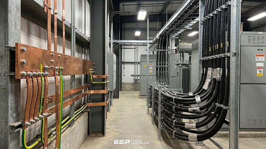 Earthed vs. Unearthed Cables in LV and MV Applications
Understanding how transient overvoltages behave during asymmetric fault conditions is extremely important for specifying the correct insulation thickness and shielding configuration to prevent catastrophic dielectric breakdown.
In electrical power distribution, the terminology distinguishing “earthed” from “unearthed” cables frequently causes confusion, as it does not typically refer to whether the cable possesses a physical metallic earth screen or armor. Instead, it defines the cable’s insulation grading based on the operational grounding philosophy of the wider electrical network.
The central responsibility of any power cable is twofold: its metallic core must conduct the required ampacity with minimal I2R thermal losses, while its polymeric dielectric insulation must continuously withstand the prevailing electrical stress without succumbing to partial discharge or electrical treeing.
The ability of the cable’s dielectric to withstand this violent vector shift without rupturing is entirely dependent on whether it was specified as an earthed or unearthed cable.
- Fundamental Definitions: U0, U, and Um
- Low Voltage Applications and Grounding Topologies
- Medium Voltage Systems: The Physics of Voltage Shift
- IEC 60183 Categories and Insulation Coordination
- Design and Construction of Earthed MV Cables
- Design and Construction of Unearthed MV Cables
- Practical Installation and Termination Challenges
- Advanced Diagnostics and Partial Discharge (PD)
- Economic Considerations: CapEx vs OpEx
- Final Notes on Earthed vs. Unearthed Cables
- BONUS (PDF) 🔗 Download ‘Power Cable Handbook’
1. Fundamental Definitions: U0, U, and Um
To navigate the engineering specifications of Low Voltage and Medium Voltage cables, one must first establish the internationally recognized voltage designation format codified by the International Electrotechnical Commission (IEC).
It’s worth mentioning that power cables are universally specified by the syntax U0 / U (Um), where each parameter defines a specific dielectric threshold.
U0 represents the rated power-frequency voltage between any phase conductor and earth (or the metallic screen). U represents the rated power-frequency voltage between any two phase conductors. Finally, Um signifies the maximum highest system voltage for which the equipment is designed, accounting for grid fluctuations and light transients.
Thus, the cable’s dielectric barrier must be physically engineered to withstand this 173% increase in electrical stress for prolonged durations.
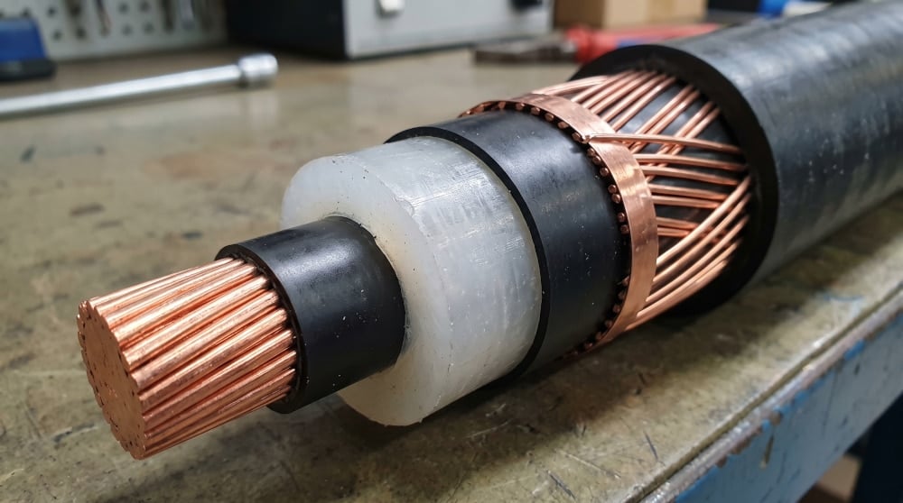
Figure 1 – Cross-section of a standard MV cable, showcasing the central copper core, translucent XLPE
2. Low Voltage (LV) Applications and Grounding Topologies
In Low Voltage applications (defined by IEC standards as operating at or below 1000V AC) the concepts of earthed versus unearthed architectures are explicitly categorized by grounding topologies: TN, TT, and IT systems.
The behavior of the electrical installation under a fault condition strictly dictates the dielectric stress placed upon the LV cable infrastructure.
TN and TT systems are solidly earthed topologies. In these configurations, the neutral point of the distribution transformer is bonded directly to the earth. When a phase conductor within an LV cable experiences an insulation failure and contacts the grounded metallic armor or tray, a massive, low-impedance fault circuit is established.
Consequently, standard 0.6/1kV LV cables are perfectly adequate for TN and TT systems, as their U0 rating of 600V easily exceeds standard 230V or 277V phase-to-ground operational voltages.
Table 1 – Low Voltage (LV) Applications and Grounding Topologies
| LV Topology | Grounding Status | Behavior on 1st Ground Fault | Insulation Stress on Healthy Phases | Cable Specification Suitability |
| TN-S / TN-C | Solidly Earthed | Immediate protective device trip | Minimal transient spike | Standard 0.6/1kV is optimal |
| TT | Solidly Earthed | Immediate RCD/breaker trip | Minimal transient spike | Standard 0.6/1kV is optimal |
| IT (400V) | Unearthed / Isolated | Alarm only; process continues | Rises to 400V to ground | 0.6/1kV is sufficient (400V < 600V) |
| IT (690V) | Unearthed / Isolated | Alarm only; process continues | Rises to 690V to ground | Requires 1.8/3kV cable (690V > 600V) |
The engineering paradigm changes drastically in an IT (Isolé Terre) system, which is intentionally unearthed or grounded through a very high impedance. IT systems are deployed in mission-critical environments, such as hospital operating theaters, underground mining, and continuous chemical processing plants—where an immediate loss of power from a single ground fault would be catastrophic.
In an IT network, a single-line-to-ground fault produces only a tiny capacitive charging current. However, the voltage of the remaining two healthy phases to ground instantly rises to equal the full line-to-line voltage.
If the IT system operates at 690V, the healthy phases will sit at 690V with respect to earth until the fault is located and repaired. Because a standard LV cable only features a U0 rating of 600V, utilizing it in a 690V IT system guarantees the insulation will be severely overstressed, accelerating dielectric degradation.
Thus, IT systems at this voltage tier require unearthed-rated cables, typically specified at 1.8/3kV.
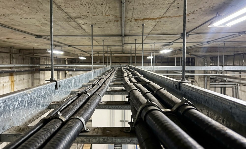
Figure 2 – Heavy-duty low voltage armored cables routed along a galvanized tray in an industrial plant. In IT systems, these must withstand sustained overvoltages.
3. Medium Voltage (MV) Systems – The Physics of Voltage Shift
As we talk about Medium Voltage distribution (typically 1kV to 35kV), the physics of insulation coordination become significantly harder. At these elevated voltages, the electrical field radiating from the conductor core exerts immense stress on the polymer chains of the Cross-Linked Polyethylene (XLPE) or Ethylene Propylene Rubber (EPR) insulation.
The primary determinant of cable longevity in MV networks is how effectively the system manages the violent geometric shift of voltage phasors during a single-line-to-ground fault (SLGF).
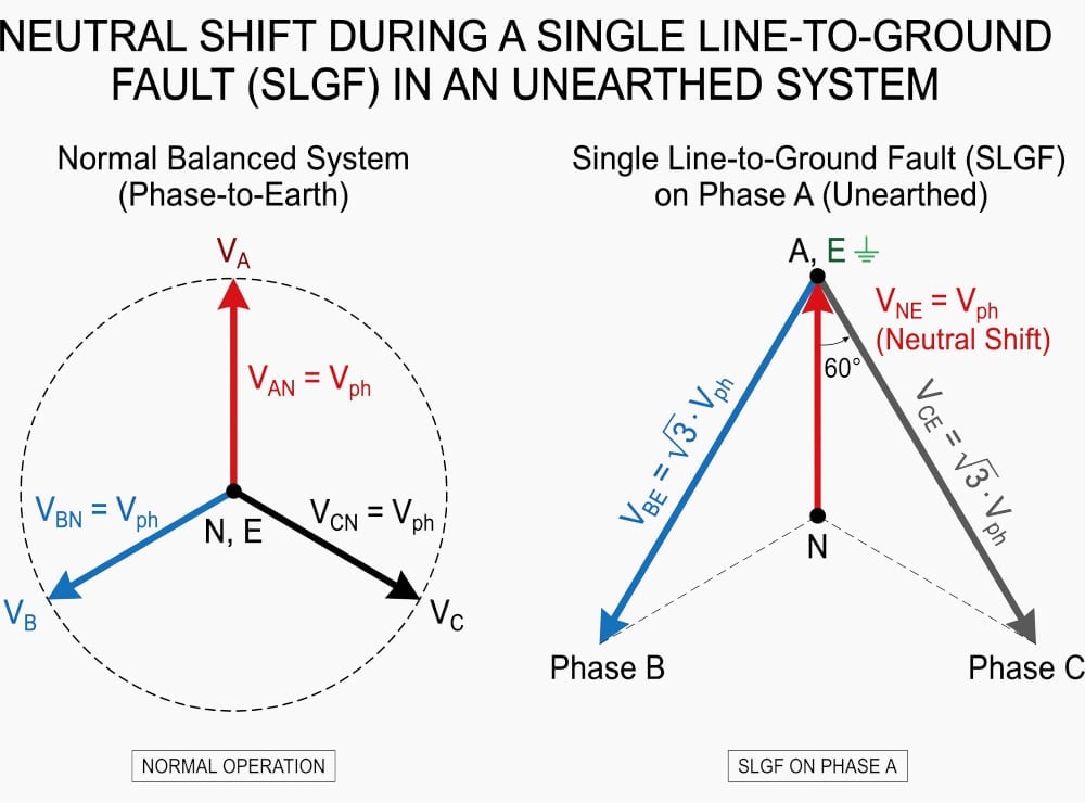
Figure 3 Illustrates the neutral shift in an unearthed network during a Single Line-to-Ground Fault (SLGF).
Let’s analyze Figure 3.
Left side (Normal Operation): Shows a balanced system where the neutral point N and earth potential E are identical (0V) at the center of the vector system. The phase-to-ground voltages (VAN, VBN, VCN) are equivalent to the standard phase voltage (Vph).
Right side (Single Line-to-Ground Fault on Phase A): When a fault occurs on phase A in an unearthed system, the ground potential E is forced to the potential of Phase A (E = A), while the source’s neutral N remains physically isolated.
Additionally, the phasor angle between the healthy phase-to-earth voltages collapses from 120° to 60°.
Figure 3 – Phasor diagram illustrating the neutral shift during an SLGF in an unearthed network
However, when an SLGF occurs on an unearthed network (or a network compensated via an arc suppression Petersen coil), the fault current is severely limited. Because the fault is not a solid short circuit to the source, the protective relays do not trip the circuit breakers immediately.
Instead, the entire capacitive network of the grid shifts in relation to earth. The faulted phase (L1 in Figure 3) is now electrically tied to earth potential (0V).
If standard cables designed for earthed networks are utilized in this scenario, their relatively thin insulation will be subjected to nearly double the electrical stress they were designed to handle.
This intense electric field can cause localized heating, accelerate water treeing if moisture is present, and initiate microscopic partial discharges within any microscopic voids inside the XLPE matrix, ultimately leading to catastrophic dielectric puncture and grid failure.
Useful Reading – Sheet-By-Sheet Analysis of 10kV Motor Control Centre (MCC) Technical Drawings in EPLAN
Sheet-By-Sheet Analysis of 10kV Motor Control Centre (MCC) Technical Drawings in EPLAN
4. IEC 60183 Categories and Insulation Coordination
To mathematically quantify the relationship between fault clearing times and dielectric thickness, the International Electrotechnical Commission developed the IEC 60183 standard (“Guide to the selection of high-voltage cables“). This critical document classifies electrical networks into three distinct operating categories based directly on their earthing philosophy and relay protection speed.
These categories dictate whether an engineer must specify an “earthed” cable or an “unearthed” cable for a given installation.
Category A encompasses solidly earthed networks. In these systems, protective switchgear is configured to clear any earth fault rapidly—almost always within one minute, and typically within milliseconds. Because the healthy phases are exposed to the √3 voltage shift for such an exceedingly brief duration, there is insufficient time for the XLPE to degrade thermally or electrically.
Category B defines networks that operate under fault conditions for a limited duration. These include unearthed systems, high-resistance grounded systems, and Petersen-coil compensated networks. The standard permits these systems to operate with an active earth fault for up to one hour, with a strict maximum accumulation of 8 hours of faulted operation per year.
To withstand this prolonged 173% overvoltage without failing, the cable must have substantially thicker insulation. Thus, “unearthed” cables are specified, rated for U0 = U. For the same 11kV network, a Category B cable would be specified as 11/11kV (sometimes designated as 8.7/15kV in IEEE markets).
Table 2 – IEC 60183 Categories and Insulation Coordination
| IEC Category | Network Grounding Type | Maximum Fault Duration | Required U0 Rating | Example (11kV System) |
| Category A | Solidly Earthed / Low Z | < 1 minute (Immediate Trip) | U0 = U / √3 (100% level) | 6.35/11 (12) kV |
| Category B | Unearthed / High Z | < 1 hour (max 8 hrs/year) | U0 = U (173% level) | 11/11 (12) kV |
| Category C | Isolated (Continuous process) | > 1 hour (Indefinite) | Requires highest insulation | 19/11 (12) kV (or custom) |
Category C is the most extreme classification, representing networks where ground faults might persist for undefined durations exceeding the allowances of Category B. This is common in highly remote mining operations, marine vessels, or offshore drilling platforms where locating and repairing the fault takes immense time, yet shutting down the grid poses life-safety or massive economic risks.
In these applications, the cable’s fundamental U0 rating must greatly exceed the standard system phase-to-ground voltage, leading to incredibly thick and heavy cable constructions that are difficult to route and terminate, but offer unparalleled dielectric robustness under duress.
Suggested Course – Practical Course for Designing LV Distribution Systems in Houses and Commercial Buildings
Practical Course for Designing LV Distribution Systems in Houses and Commercial Buildings
5. Design and Construction of Earthed MV Cables
Earthed MV cables, designed explicitly for Category A solidly grounded systems, represent the baseline of electrical cable manufacturing. Because the protective relays guarantee that any asymmetric fault will be eradicated within milliseconds, the manufacturer can optimize the thickness of the XLPE or EPR insulation solely for standard continuous power-frequency voltage.
This results in a leaner, more cost-effective product.
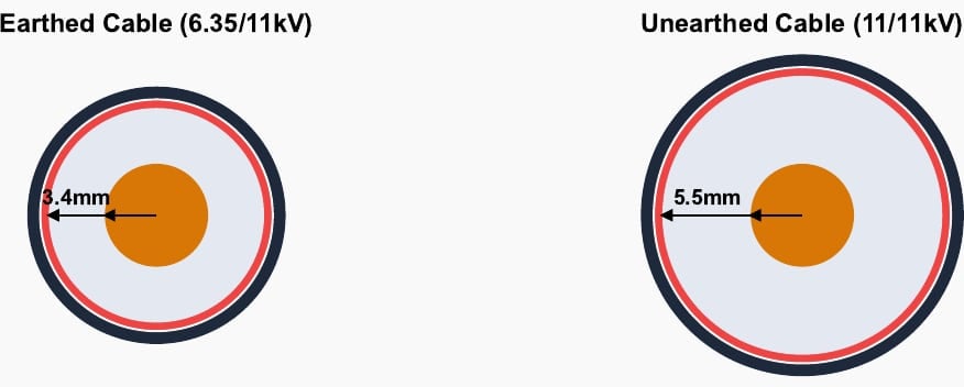
For example, taking a standard 11kV network, an earthed cable is specified as 6.35/11kV. According to IEC 60502-2, the nominal insulation thickness for a typical cross-section (e.g., 185mm2 copper conductor) is approximately 3.4 mm.
This relatively thin dielectric layer is entirely sufficient to block the 6.35kV potential difference between the energized copper core and the grounded metallic screen under steady-state load conditions.
The primary advantage is a significantly reduced overall outer diameter (OD). A smaller OD translates directly into a lighter cable, requiring less heavy machinery to pull through underground ducts.
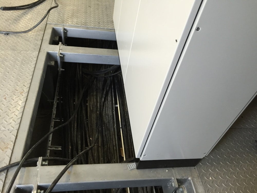
Furthermore, it results in a tighter minimum bending radius, which is a critical metric when maneuvering stiff, heavily armored power cables through the cramped sub-floor trenches of industrial switchgear rooms.
Figure 4 - A common substation switchgear room. The tight confines beneath these cabinets make the smaller bending radii of Category A (earthed) cables highly advantageous during installation.
Internally, earthed cables in the MV range almost universally utilize a radial field construction. Each individual phase conductor is extruded with an inner semi-conductive screen, the XLPE insulation, and an outer semi-conductive screen, followed directly by a metallic earth shield (usually copper wires or copper tape).
This ensures that the electrical field radiates perfectly outward from the conductor in a uniform circle, terminating exactly at the grounded screen.
There are no tangential electrical fields between the phases, meaning the filler materials and outer protective sheaths are under absolutely zero electrical stress, serving only mechanical and waterproofing purposes.
Highly Recommended - Shape up your technical skills in your everyday life as an LV/MV/HV electrical engineer
6. Design and Construction of Unearthed MV Cables
Unearthed MV cables, engineered to satisfy the rigorous demands of Category B and Category C networks, are fundamentally heavier, thicker, and more robust structures. Knowing that the network will intentionally operate with one phase grounded for up to an hour, the dielectric must act as an impervious barrier against the full 173% line-to-line voltage.
In the cable industry, this is often referred to as specifying a "173% insulation level".
While a 2.1 mm increase might appear mathematically trivial, when applied radially to a circumference, and then multiplied across all three phases in a multi-core cable assembly, it dramatically increases the aggregate volume, mass, and cross-sectional footprint of the finished product.
Figure 5 - Comparative scale of insulation thickness for identical conductor sizes
This increased volume requires substantially more extrusion material, larger interstitial fillers to maintain a circular profile, and larger quantities of steel wire armor (SWA) to encapsulate the wider assembly. From an electrical perspective, the altered geometry significantly changes the capacitive signature of the network.
The thicker insulation reduces the capacitance per meter of the cable. In highly extensive networks, this shift in distributed capacitance directly impacts the tuning calculations required for Petersen coils, which must be perfectly calibrated to inject inductive current that precisely cancels out the network's capacitive fault current during an earth fault.
However, under the extreme asymmetric stress of an unearthed fault, belted cables suffer from intense tangential electrical fields that quickly break down the interstitial fillers.
Today, individually screened constructions are universally mandated for unearthed MV applications.
Related Study - The art of arc-protection relaying in MV applications
7. Practical Installation and Termination Challenges
The theoretical differences between these cable types manifest as intense practical challenges during field installation, particularly at the points of termination and jointing. A cable is most vulnerable not along its uninterrupted length, but at its ends, where the outer metallic screen is stripped back to expose the insulated conductor for connection to switchgear busbars or transformer bushings.
At this precise truncation point, the electrical field ceases to be uniformly radial and violently diverges outward, creating a high-stress concentration zone known as the triple-point.
If the termination kit was incorrectly specified for an earthed system, this immense stress will rapidly ionize the surrounding air, leading to surface tracking, corona discharge, and an explosive flashover that can obliterate the switchgear compartment.
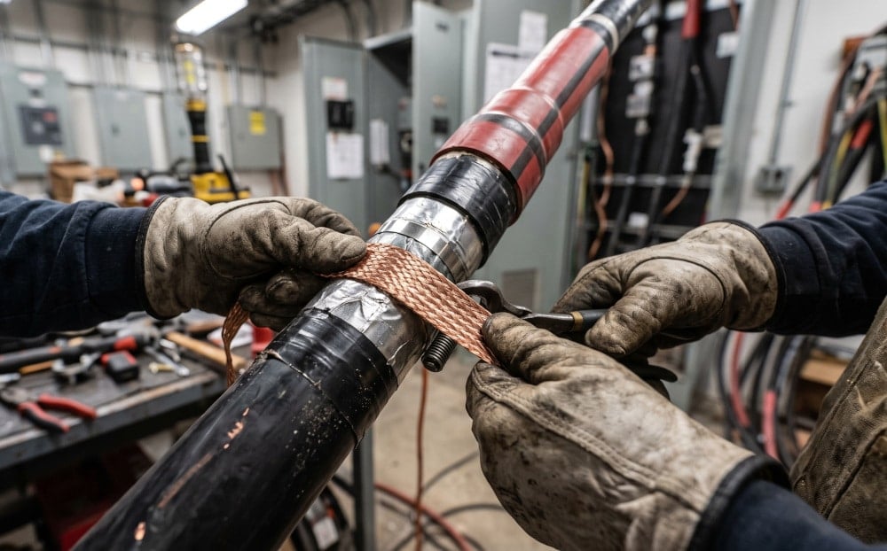
Figure 6 - Substation technician attaching a grounding braid to the copper screen of an MV termination. Precise stress control at this junction is important in unearthed networks.
Furthermore, the metallic screens of single-core MV cables present unique challenges regarding circulating currents. The alternating magnetic field generated by the high alternating currents in the central core induces substantial voltages in the parallel metallic screens.
If the screens are bonded to earth at both ends (solid bonding), these induced voltages drive massive circulating currents through the shield, generating intense I2R heat losses that thermally degrade the insulation from the outside in.
Unearthed cables, operating under highly asymmetric fault conditions, generate chaotic induced voltages on the screens during an SLGF, requiring highly sophisticated surge arresters (sheath voltage limiters) at the cross-bonding boxes to prevent shield puncture.
Useful Tool (Excel) - Cables Database tool for design of cables connections, laying and terminations
Cables Database tool for design of cables connections, laying and terminations
8. Advanced Diagnostics and Partial Discharge (PD)
Because unearthed cables are subjected to immense voltage elevations during faults, the integrity of their polymer matrix is scrutinized far more aggressively than their earthed counterparts. The primary enemy of any solid dielectric is Partial Discharge (PD), an occurrence of microscopic electrical sparks that occur within tiny air voids, impurities, or moisture trees trapped inside the XLPE during manufacturing.
According to Paschen's law, a void that remains electrically inert under the standard U0 stress of daily operation may suddenly exceed its breakdown voltage threshold when subjected to the 173% overvoltage of a network fault.
To detect these invisible threats before they cause catastrophic failure, engineers utilize Very Low Frequency (VLF) offline testing, typically at 0.1 Hz, to measure Tangent Delta (Dielectric Loss Angle) and map PD locations. The testing protocols are drastically different for earthed versus unearthed cables.
Useful Guide (PDF) - Online partial discharge measurements as a proven way to diagnose power cables
Online partial discharge measurements as a proven way to diagnose power cables
8.1 Regulatory Standard Testing Parameters (IEEE 400.2 / IEC 60502-2)
When performing VLF withstand testing on a newly installed cable, the applied test voltage is a direct multiple of the cable's U0 rating. Because an unearthed cable inherently possesses a higher U0 rating (e.g., 11kV rather than 6.35kV for the same network), the diagnostic test equipment must inject a correspondingly higher peak voltage to adequately stress the thicker insulation matrix.
Testing an unearthed cable using earthed parameters will result in a false-positive pass, leaving the network vulnerable to sudden failure during its first ground fault event.
In unearthed networks, these monitoring systems are programmed to cross-reference PD data with the zero-sequence voltage measurements from the substation busbar.
If a ground fault occurs and the network enters an overvoltage state, the monitoring system watches specifically for dormant voids that suddenly begin discharging under the elevated stress, providing operators with actionable intelligence regarding which specific cable segments are closest to catastrophic breakdown.
Further Study - The good and bad practices in the commissioning of current transformers in a substation
The good and bad practices in the commissioning of current transformers in a substation
9. Economic Considerations: CapEx vs OpEx
The choice between specifying an earthed or unearthed cable architecture ultimately descends into a complex cost-benefit analysis weighing Capital Expenditure (CapEx) against Operational Expenditure (OpEx) and the monetary value of uninterrupted production. Earthed systems utilize cheaper, thinner cables and simpler protective relays, representing a massive CapEx saving during construction.
However, they guarantee complete power loss to the affected circuit immediately upon a fault.
If an earth fault occurs in a steel mill, an unearthed system allows the batch of molten metal to finish processing over the next two hours, preventing millions of dollars in ruined product and hardened steel destroying the furnace.
Table 3 - Economic Considerations: CapEx vs OpEx
| Metric | Earthed Cable System (TN / Category A) | Unearthed Cable System (IT / Category B) |
|---|---|---|
| Cable Procurement Cost | Lowest (Optimized thin insulation) | High (Thick 173% insulation level) |
| Installation Difficulty | Moderate (Tighter bend radius, lighter) | High (Stiff, heavy, large cross-section) |
| Protection Complexity | Simple overcurrent/earth fault relays | Complex directional/capacitive relays |
| Cost of a Fault (OpEx) | Massive (Total immediate loss of process) | Minimal (Process continues, repaired later) |
10. Final Notes on Earthed vs. Unearthed Cables
In summary, the distinction between earthed and unearthed cables transcends simple nomenclature. It is a fundamental engineering parameter that bridges network grounding philosophy with material science and dielectric physics. Earthed cables, optimized for systems that instantly isolate electrical faults, rely on the speed of mechanical circuit breakers to protect their thin dielectric barriers from overvoltage destruction.
They are the backbone of utility distribution networks where temporary localized blackouts are acceptable.
Understanding this delicate balance between network relay protection speeds, transient overvoltages, and cable insulation thickness is the hallmark of professional power systems engineering, ensuring that critical infrastructure remains both safe and economically viable under the most extreme operating conditions.
Learn more - Why do existing substations need to be automated
9. BONUS (PDF): Power Cable Handbook
Download: Power Cable Handbook (for premium members only):
Related electrical guides & articles





Edvard Csanyi
Hi, I'm an electrical engineer, programmer and founder of EEP - Electrical Engineering Portal. I worked twelve years at Schneider Electric in the position of technical support for low- and medium-voltage projects and the design of busbar trunking systems.I'm highly specialized in the design of LV/MV switchgear and low-voltage, high-power busbar trunking (<6300A) in substations, commercial buildings and industry facilities. I'm also a professional in AutoCAD programming.
Profile: Edvard Csanyi