Earthing typology of the plant
In order to break a short-circuit current in a d.c. system, it is necessary to connect the circuit breaker (CB) poles in a suitable way. To carry out this operation, it’s necessary to know the earthing typology of the plant. Such information allow any possible fault condition to be evaluated and consequently the most suitable connection type to be selected according to the other characteristics of the plant (short-circuit current, supply voltage, rated current of the loads, etc.).
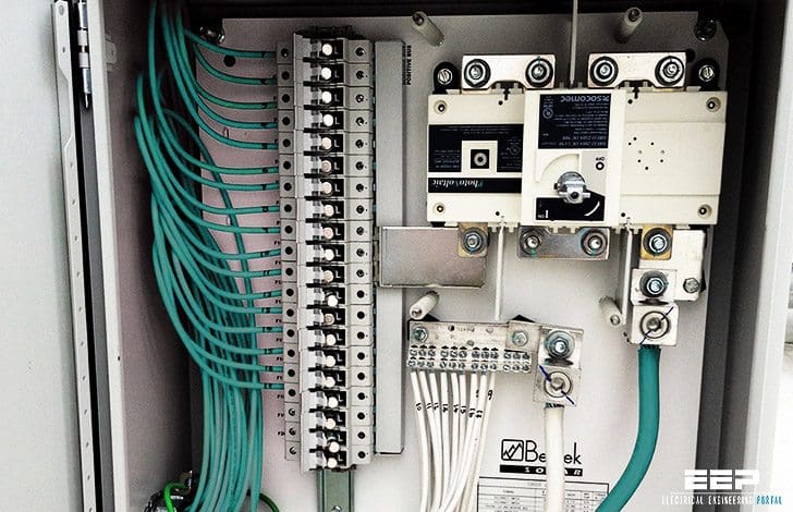
This technical article will give for each network typology these fundamental information – Description of the network and fault typologies.
Let’s discuss now the three most common network typologies in DC networks:
- Network insulated from earth
- Network with one polarity earthed
- Network with the middle point of the supply source connected to earth
1. Network insulated from earth
This type of network represents the easiest connection to carry out, since no connection between the battery polarities and earth are provided. These types of systems are widely used in those installations where earthing results to be difficult, but above all where service continuity is required after a first earth fault (see the following paragraphs).
On the other hand, since no polarities are earthed, this connection presents the inconvenience that dangerous overvoltages could occur between an exposed conductive part and earth due to static electricity (such hazards can be limited by overload dischargers).
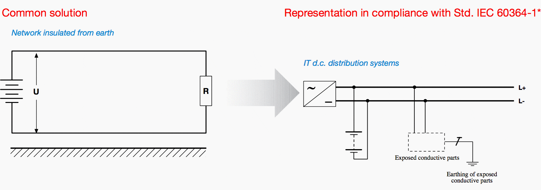

* such analogy is valid for the earthing of the supply source only and not for the earthing of the exposed-conductive-parts; besides, as far as the prescriptions concerning indirect contacts are concerned, please refer to Std. IEC 60364-4.
Fault typologies in a network insulated from earth
Fault A:
The fault between the two polarities is a short-circuit current fed by the full voltage U. The breaking capacity of the circuit breaker shall be chosen according to the short-circuit current relevant to such fault.


Fault B:
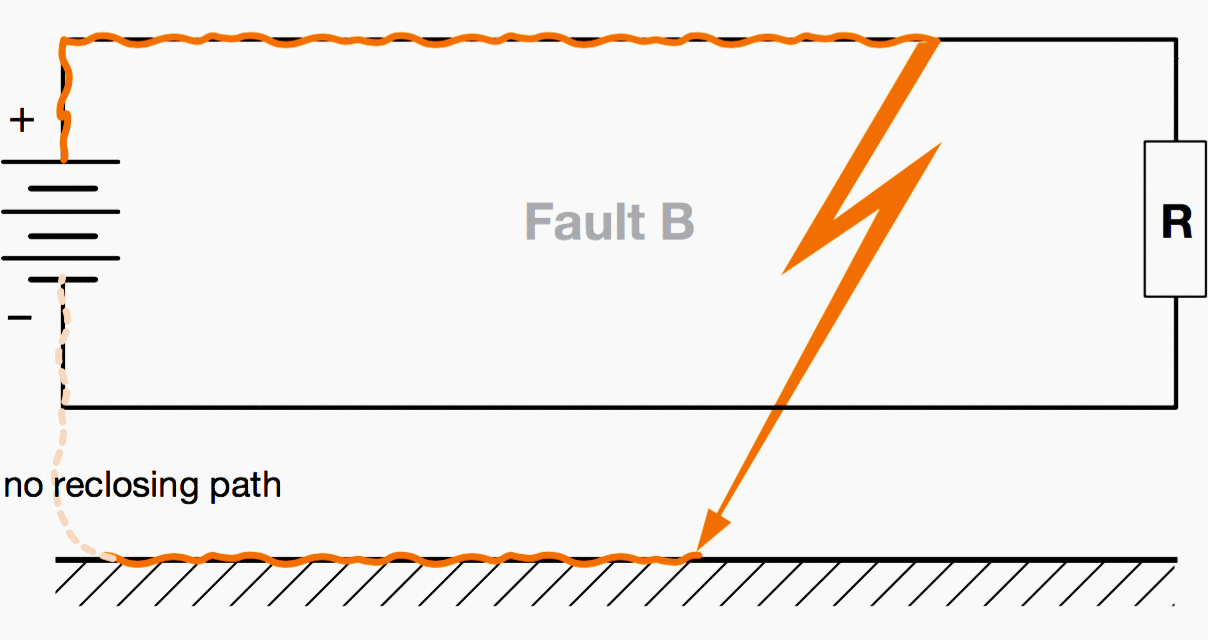
The fault between a polarity and earth has no consequences from the point of view of the plant operation since such current has no reclosing paths and consequently it cannot circulate.

Fault C:
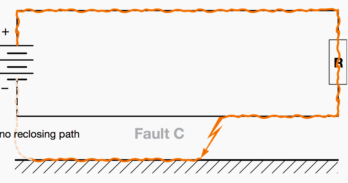
Also this fault C (as fault B) between a polarity and earth has no consequences from the point of view of the plant operation.

Double fault (fault B + fault C):
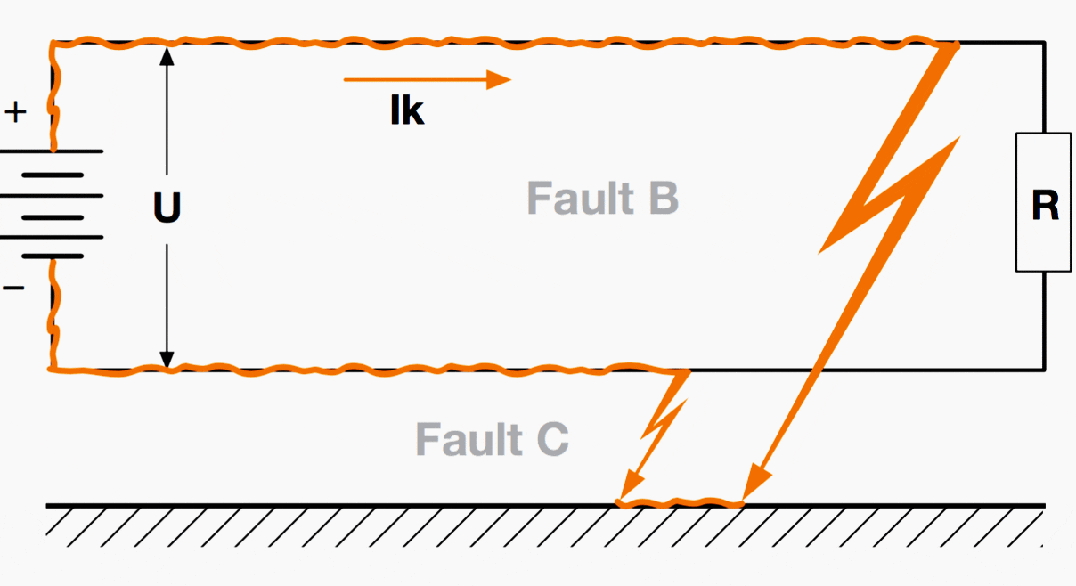
In case of a double fault, as shown in the figure, the current might circulate and find a reclosing path. In this case, it is advisable that a device capable of signaling an earth fault or a decrease of the insulation to earth of a polarity is installed in the plant
Thus, the fault is eliminated in good time to prevent the occurrence of a second earth fault on the other polarity and the consequent total inefficiency of the plant due to the tripping of the CB caused by the short-circuit generated on the two polarities to earth.

Conclusions //
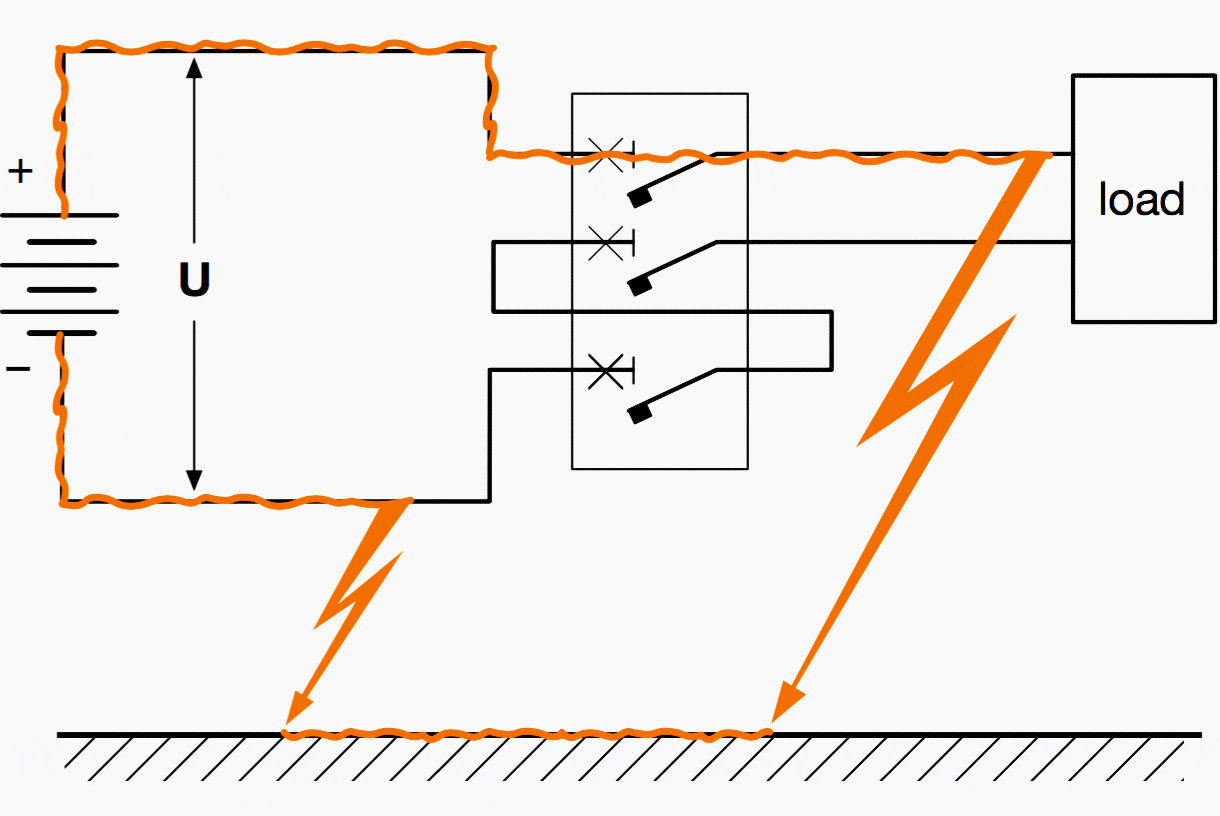
With this typology of network, the fault type which affects the version and connection of the CB poles is fault A (between the two polarities). In an insulated network it is necessary to install a device able to signal the presence of the first earth fault so that it can be eliminated to avoid any problem arising from a second earth fault.
In fact, in case of a second earth fault, the CB could have to interrupt the fault current, under the worst conditions, with the full voltage applied to a single polarity and consequently with an insufficient arc voltage (see figure below).

2. Network with one polarity earthed
This typology of network is obtained by connecting to earth one polarity (either the negative or the positive one).
This connection type allows the overvoltages due to static electricity to be discharged to earth.
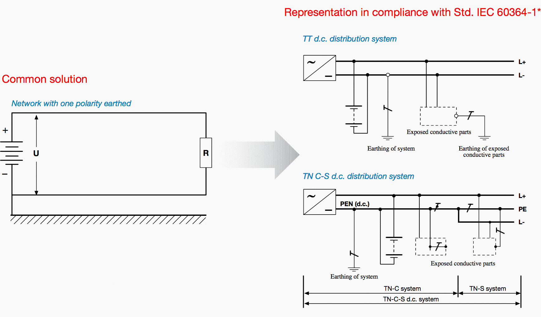

*such analogy is valid for the earthing of the supply source only and not for the earthing of the exposed-conductive-parts; besides, as far as the prescriptions concerning indirect contacts are concerned, please refer to Std. IEC 60364-4.
Fault typologies in a network with one polarity earthed
(in the following examples the earthed polarity is the negative one)
Fault A:
The fault between the two polarities is a short-circuit current fed by the full voltage U. The breaking capacity of the circuit breaker shall be chosen according to the short-circuit current relevant to such fault.


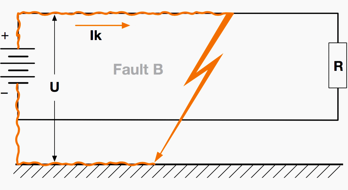
Fault B:
The fault on the non-earthed polarity sets up a current involving the overcurrent protections as a function of the soil resistance.

Fault C:
The fault on the earthed polarity sets up a current which affects the overcurrent protections as a function of the soil resistance.
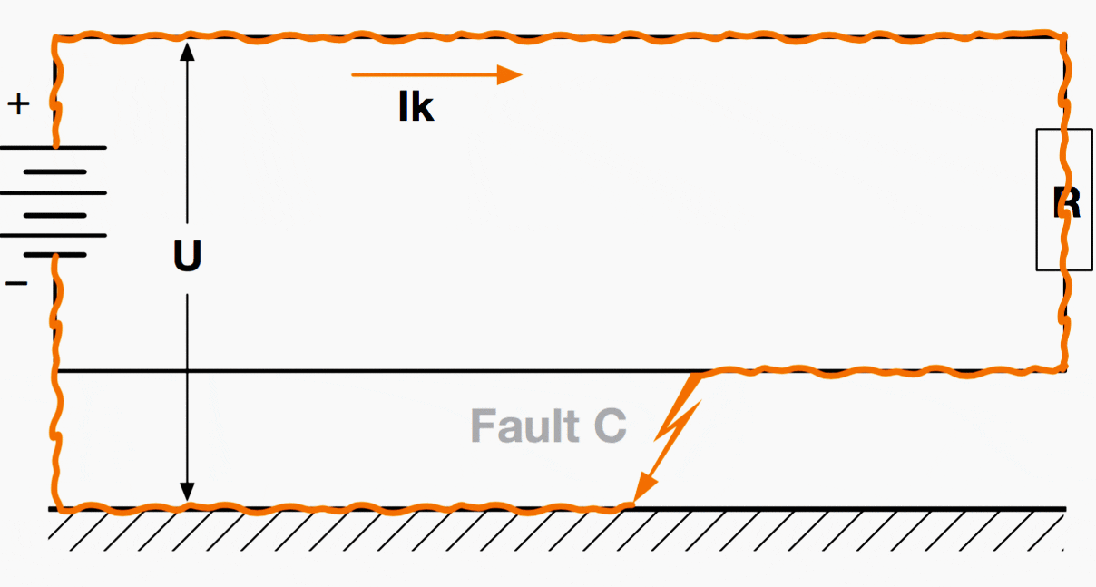

Conclusions //
With this typology of network, the fault type which affects the version of the CB and the connection of the poles is fault A (between the two polarities).
But it is necessary to take into consideration also the fault between the non- earthed polarity and the earth itself (fault B) since, as described above, a current (with the value depending also by the impedance of the soil and consequently difficult to assess) could ow at full voltage.
For this reason, all the CB poles necessary for protection shall be connected in series on the non-earthed polarity.
3. Network with the middle point of the supply source connected to earth
This typology of network is obtained by connecting the middle point of the battery to earth. This type of connection reduces the value of static overvoltages, which otherwise could be present at full voltage in an insulated plant.
The main disadvantage of this connection, if compared with other types, is that a fault between a polarity, both a negative as well a positive one, and earth gives rise to a fault current at a voltage U/2.


*such analogy is valid for the earthing of the supply source only and not for the earthing of the exposed-conductive-parts; besides, as far as the prescriptions concerning indirect contacts are concerned, please refer to Std. IEC 60364-4.
Fault typologies in a network with the middle point connected to earth
Fault A:
The fault between the two polarities is a short-circuit current fed by the full voltage U. The breaking capacity of the circuit breaker shall be chosen according to the short-circuit current relevant to such fault.


Fault B:
The fault between the polarity and earth sets up a short-circuit current lower than that relevant to the fault between the two polarities, since it is supplied by a voltage equal to U/2 depending on the soil resistance.
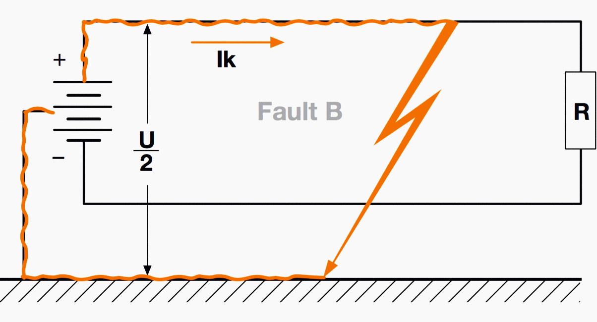

Fault C:
In this case, the fault is analogous to the previous case, but it concerns the negative polarity.


Conclusions //
With this typology of network the fault which affects the version of the CB and the connection of the poles is fault A (between the two polarities).
However, also the fault between a polarity and earth (with reference to the above diagrams) should be taken into consideration because, as previously described, a current (the value of which depends also on the impedance of the soil) could flow at a voltage equal to U/2.
In a network with the middle point of the supply connected to earth, the circuit breaker must be inserted necessarily on both the polarities.
Reference // ABB circuit breakers for direct current applications







Nice article! Thank you for your sharing!
Nur
Great article.
For information, the main component on the combiner is a disconnect switch; to make and break under load conditions and to provide safety isolation – as per UL98B standard and comply with NEC Atr. 690.
Short circuit protection is done via the fuses that are shown on the left side of the combiner (gPV fuses, rated up to 50kA).
Best regards,
David.
Dear Edvard
Excelent article.
It must be borne in mind that, as overcurrent detection in dc system is either difficult to detect – due to arc resistance – and because the current does not pass through zero, the best way to characterize a dc fault is by means of voltage detection.
This implies the use of expensive breakers.
If the system is connected according to IEC 60364-1, you can remove the batteries and leave the dc source connected. The short circuit current will be limited by the source current and it can be switched with less harm to the breakers.
Rgds
Emmanuel