
Estimated Study Time: 5 minutes
Protection from fault current
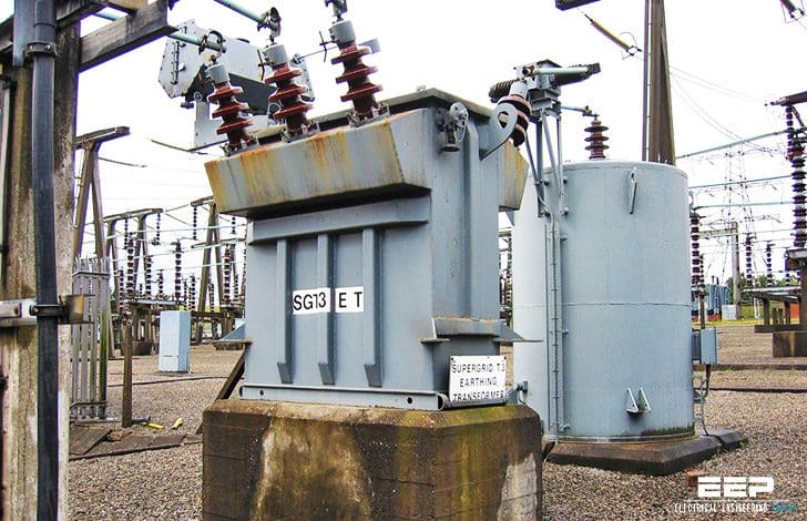
Earthing Transformer or grounding transformer is the neutral grounding transformer – star connected on the primary and has an open delta on secondary. Open Delta has two terminals. A resistor is connected across these two terminals. Whenever a fault occurs, voltage will be induced in the open delta and there will be a voltage drop in the resistor connected.
This voltage drop will be sensed by the earthing transformer connected across this resistor. At the secondary of the earthing transformer we have the neutral displacement relay which will give a trip signal or an alarm whenever its settings exceed a particular value.
Earthing transformer can also be called a large Potential transformer (Open delta PT).
Representation in SLD
Connection diagram
The best way to ground an ungrounded delta system (existing or new) is to derive a neutral point through grounding transformers as shown in figure above. The resistor inserted in the “broken delta” leg is reflected to the primary underground fault conditions and limits the current to a nominal value as dictated by its design.
The three lights across each individual transformer will constitute a version of the normal ground detection scheme currently employed on ungrounded systems.
The voltage across the broken delta is simply the sum of system phase to ground voltages, or 3V0.The Y side of the Y-ground/Broken delta VT can either be directly connected to the high voltage terminals or to the secondary of a main step down VT.
It is common to place a resistor in the broken delta as shown in above figure. One rationale for the resistance is that the resistance stabilizes the measured voltage.
It does this by:
- Reducing the risk of ferroresonance
- Act as a grounding bank/transformer.
Voltages during a ground fault
Referring to phaser diagram:
- VAG = VAN + VNG = K<0 + 0 /Equation 1/
- VBG = VBN + VNG = K<-120 + 0 /Equation 2/
- VCG = VCN + VNG = K<120 + 0 /Equation 3/
For a phase A to ground fault, VAN = 0, and the voltage across the neutral resistor that is VNG is essentially the negative of the Phase A to neutral voltage.
Mathematically:
- VAG = 0 since Phase a is faulted
- So: VAN + VNG = 0
- VNG = -VAN = – K<0 = 1<180 /Equation 4/
Substituting equation – 4 in equation – 2
- VBG = VBN + VNG = K<-120 + K<180 = 1.732K<150 /Equation-5/
Similarly substituting equation – 4 in equation -1
VCG = VCN + VNG = K<120 + K<180 = 1.732K<150 /Equation-6/
Equation 5 and 6 proves that voltage of healthy phase rises by 1.732 times during phase to ground fault in one phase.
Sum of the three phase voltage will be:
= VAG + VBG + VCG = 0 + 1.732K<-150 + 1.732K<150 = 3K<180 /Equation-7/
Since broken/open delta sum up the three phase voltage so voltage of equation 7 will be transformed to open delta secondary side from the Y grounded primary side.
V Broken Delta = V Primary / Turn ratio = (1/turn ratio) 3K<180 /Equation-8/
Equation 8 can be generalized as:
V Broken Delta =(1/Turn ratio) (3 V L-G System) < (Un faulted phase angle + 180)
Resistance Selection
To obtain the maximum capability of the resistor to dampen system transients and dampen ferroresonant circuits, a typical approach to sizing the resistor is to utilize one that can handle all the power that the transformer can supply during a full neutral offset.
Related electrical guides & articles


Asif Eqbal
Bachelor of Engineering in Electrical & Electronics engineering, from Manipal University, (Karnataka), India in 2006. Presently involved in the design of EHV outdoor substation and coal fired thermal power plants for more than seven years. Motto of joining EEP as a contributor is to share my little engineering experience and help the budding engineers in bridging the conspicuous gap between academics and Industrial practice. “If you have knowledge, let others light their candles with it, so that people who are genuinely interested in helping one another develop new capacities for action; it is about creating timeless learning processes".Profile: Asif Eqbal

What is the current magnitude difference for the zero sequence current contribution between two transformers that both have the same impedance, where one is a Wye primary /Broken Delta secondary grounding bank, with a resistor inserted in the broken Delta, versus a conventional Wye primary /Delta secondary grounding bank, during a line to ground fault condition on the primary wye side of the grounding transformers?
Merci !
The successful operation of distribution network with earthing transformers calls for timely operation of protective devices. Fault current for higher duration will lead to damage to earthing transformer . We have come across frequent failures due to high resistance faults taking longer time to clear.For utility , it is essential to have spare earthing transformers , to restore supply during such failures.
what is the effect of not earthing the transformer at the primary side?
I have a generator connected to a step up delta star transformer and when I close the generator breaker opens. What could this be?
I HAVE A QUESTION ABOUT WHAT IS HAPPENING IN A SITUATION WHEN THERE IS A LOOS OF ONE PHASE OR TWO PHASES TO A TRANSFORMER FOR EXAMPLE 22\0.4 Dyn-11 .
what is the voltages ( line and phases )in the primery and the secondery in perticular ?
shay
In order to develop our approved subdivision of 129 home sites in western Arizona, USA, the local power company may require of us to bring in a “system neutral” in order to serve our future homes. Because the “system neutral” is many miles away, the cost to bring it to the property will no doubt be prohibitive. Will an adequately sized “grounding bank” work as well and would it not be less expensive overall? I am not an electrical engineer of formal education, so your reply in the simplest terms would be appreciated. If you can’t imagine any cost benefits without knowing the cost of “importing” a system neutral from the power company, please just provide us with your opinion of the sufficiency of a “ground bank” as opposed to importing a “system neutral” from the power company. Would a “grounding bank” work equally as well?
Thank you sincerely,
Is there any voltages in normal condition at output of v.t . if no then
please explain in detail…..? and also complete behave in normal condition with diagrams.
Dear Asif
Thank you for this article on earthing using star / open delta earthing transformer with resitor. Could you please also inform me how to calculate the resistance value across the open delta. e.g. 11kV/415V, 100A for 10 Sec, 250kVA continuous.
Please inform if you need any further information.
Thanks in advance
Best regards
Dear Asif,
Would it be possible to send me the detailed calculation taking as example SFMR with primary 11000V and secondary 110V.
Thx
Jeffotopo
advantage & disadvantages of it and its application also
What is the advantages and disadvantages of grounding transformer and its application also?
why do we earth the S2 or S1 of the current transformer?
Because the current loop on the secondary circuit for a current transformer is isolated, and is therefore prone to voltage rise due to capacitive coupling. The voltage levels could get to levels above cable and equipment design rating
Nice article. Good fundamentals analysis.
useful website
Why would you not use a zig-zag winding on the primary rather than a star connected winding? Would this not further limit the level of fault current flowing? What effect would it have on the open delta?
I also would like to understand more about the forces involved here as many earthing transformers fail due to mechanical strength. Your comments eher would also be of help.
There is a mistake:
where indicated: 1.732K<150 /Equation-5/
has to be: 1.732K<-150 /Equation-5/
wonderful and helpful site
Where is the reference material listed?
What about the source of the photos?
Please list does things because then you could have serious troubles with copyright and intellectual property.
No specific reference material list for this article. Photos have been picked to best suit the topic, not any project or schematic generated by specific organisation. Mathematical equation and result is what you learned in university no patent or new discovery over here.
gratitude Mr asif,
can u explain If there is a YNd11 , 12 MVA , 45/15 KV power transformer having a NGT which is 1730KVA, %z=92.7%, YNd1 transformer with no resistance across its secondary terminals , what could be the maximum earth fault current of the power transformer on 15 KV side