
What is system earthing?
The term “earthing” consists of several functions which only have “utilizing the earth” in common. Before describing the system earthing, it can be of interest to know a bit about the different types of earthing. Protective earthing is applicable mainly in electronic equipment to prevent damage or errors at the components.
 How system earthing keeps you and the network safe (photo credit: EEP)
Example of protective earthing is when a screened cable is earthed, or when an incoming signal conductor is connected to earth through a capacitor or a filter.
Protective earthing can be described as a way of protecting man from dangerous voltages. Example of protective earthing is, when the casing of e.g. a washing machine is connected to earth (green/yellow conductor) or when a row of switchgear cubicles are connected to an earth conductor, which connects the cover of the cubicle to earth.
Lightning protection can also be a part of system earthing. System earthing concern the kind of deliberate measures that connects a normally live system to earth. It is normally the zero point of the system that is connected to earth but other solutions can occur.
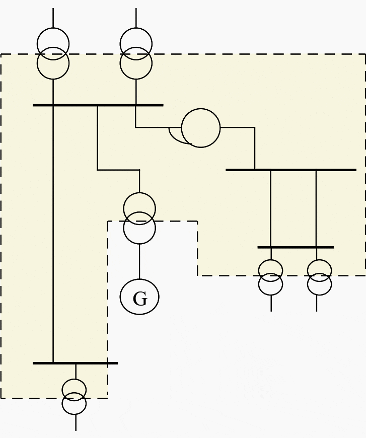
If a point in a system is earthed the whole system will be earthed as far as the galvanic connection goes. A system earthing on the contrary does not affect the parts of the network that are connected magnetically to the earthed part of the network, for example through transformers. See figure 1.
Why use system earthing
The main reason for connecting the network to an earth potential, is of course that both human beings and equipment will be protected. These are only two reasons for system earthing but many other requirements on operation reliability have to be fulfilled as well.
Some of the reasons to use system earthing are described in the following text.
1. Fix the network to earth potential
All alternating current networks are in one way or another coupled to earth through leakage capacitances. The capacitances can be so small that the network at some occasions can reach a dangerously high potential.
If a connection between the conductors in two networks with different voltage occurs, the network with the lowest voltage would get a dangerously increased voltage to earth. This can be prevented by a suitable earthing of the network with the lowest voltage.
IMPORTANT! – Even if there is no direct connection a dangerous voltage can occur due to the capacitive coupling between the two networks.
2. Reduce the fault current at earth fault
In an unearthed network a capacitive current will appear when an earth fault occurs. This derives basically from the leakage capacitance in cables and overhead lines but also generators, motors and transformers contributes.
A formula for the capacitive current IC of cables is normally stated as IC = UH/10×3 A/km, where UH is the line voltage.
If the capacitance of the network is compensated with a reactor connected to the neutral point, the current through the fault point can be drastically reduced. See figure 2. This is advantages since the damage caused by the fault current through the fault location is limited.
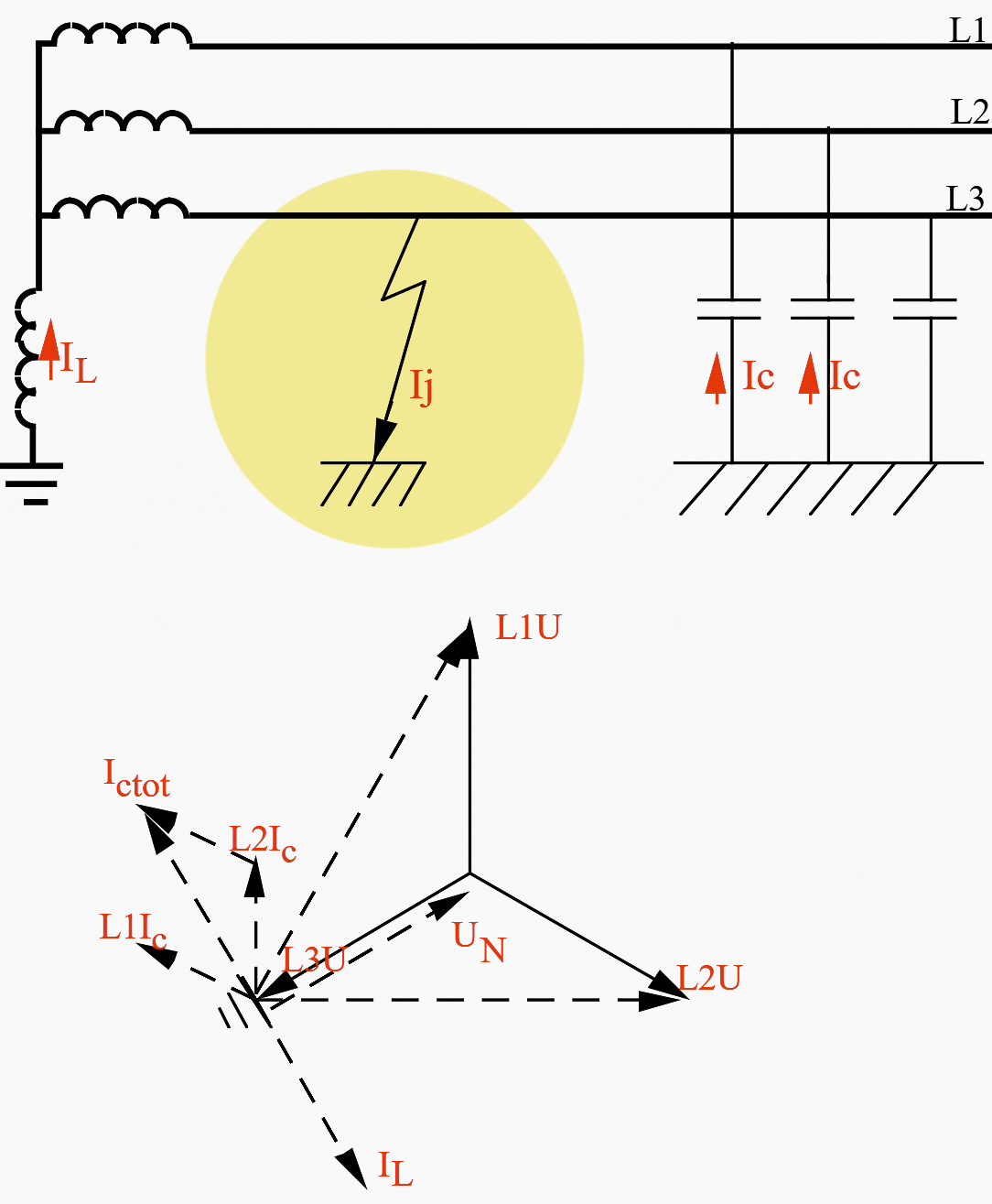
As it can be seen from Figure 2 above, resulting earth fault current Ij is very small if IL= ICTot.
3. Reduce overvoltages
The overvoltages that can be reduced through system earthing are those who depend on transient earth faults, increased neutral-point voltage and transients due to switching or lightning.
3.1 Transient earth faults
At occurring earth faults, especially in systems with small earth fault current, the conditions are such that the arc will be extinguished at the zero passage of the current. Afterwards it will be re-ignited when the voltage increases over the fault point again.
This phenomenon is in USA, called “arcing grounds”.
This is shown in Figure 3.
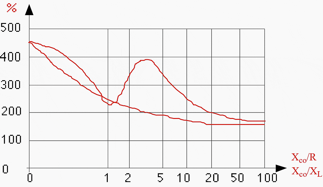
Where,
- “XC” is the leakage capacitive reactance to earth which is dependent of the total capacitance (1/wC) of the network and
- “R” is the resistance of the neutral resistor.
The figure above shows that an earthing should be performed in such a way that the earthing resistance is less or equal to the capacitive reactance to earth. If the system is earthed through a reactor its reactance should be almost equal to, or a lot less, than the total capacitive reactance to earth.
The figure shows the overvoltages that can occur during unfavorable circumstances but normally overvoltages are less. As can be seen the overvoltages in unearthed systems can be of the size, or higher than, the test voltage for new generators and motors. The risk of damaging these apparatuses will therefore be very high.
Surge arresters won’t give a reliable protection, since they will be destroyed at repeated overvoltages. A system which contains generators or motors should therefore always be earthed in some way.
3.2 Increased neutral-point voltage
In case of an earth fault in one phase in an unearthed network a phase-ground voltage will appear in the neutral-point and the other two phases will thus have their phase-phase voltage to earth.
A transformer with a direct earthed neutral-point can furthermore be equipped with graded insulation. This means that the insulation level is lower close to the neutral-point than at the line terminals which give considerable savings for big power transformers.
Recommended reading:
Neutral Point Treatment in Three-Phase Networks (Detailed Overview and Comparison)
3.3 Coupling and lightning overvoltages
Operating of switching apparatuses can create overvoltages which usually are higher than three times the nominal voltage but of short duration. The overvoltages are created through transient oscillation in the capacitance and the inductance of the circuit.
Neutral point earthing will probably not reduce the overvoltages created by switching waves or lightning. They can though distribute the voltage between the phases and reduce the possibility of a high voltage stress on the insulation between one phase and earth.
4. Simplify location of earth faults
In an unearthed network it’s often difficult to detect and clear an earth fault. Through a suitable earthing it’s possible to create an earth fault current that can be measured and also form a base for the locating of the earth faults.
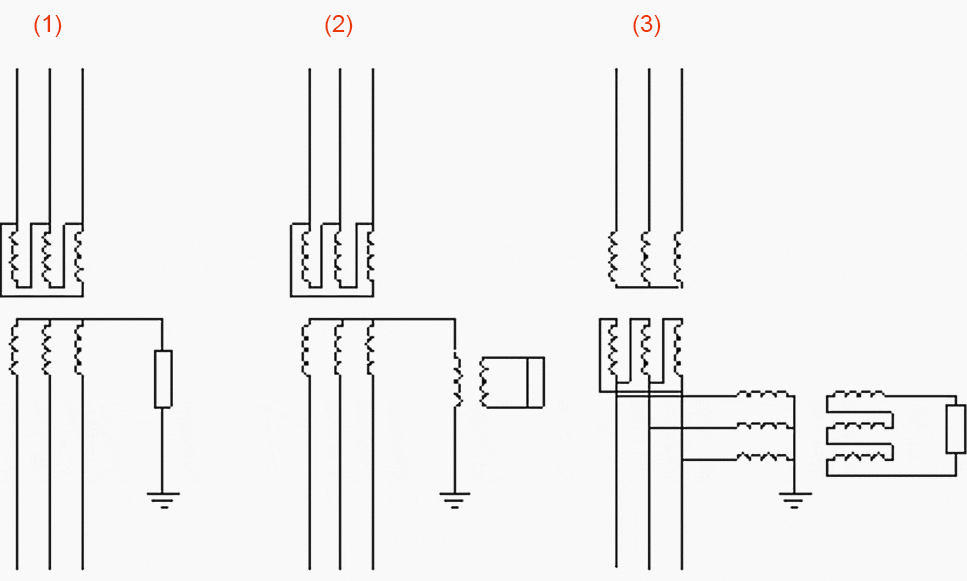
5. Avoid ferroresonance
Voltage transformers connected to an unearthed network can under particular circumstances create abnormal neutral-point voltages. The voltage transformer can then be regarded as an non-linear inductance, which goes into self-oscillation with the capacitance of the network.
This phenomenon is called “ferroresonance”.
Note that such a resistor gives the same result as a resistor with a very high resistance connected directly between the zero-point and earth. See Figure 4.
Recommended reading:
Practical solutions for preventing ferroresonance in electrical installations
Source: ABB


Thank you!
Thanks this site have been helpful
I like the page
Dear Engr Csanyi: Reduce the fault current at earth fault: the equation for the capacitive current you quoted seems to be dimensionally incorrect. A term seems to be missing:XC? Or am I missing something? Please advise