
Estimated Study Time: 10 minutes
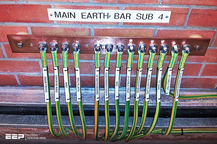
Protective conductors
As you already know, protective conductors are the main part of every earthing protection system, but the complexity of the system will increase with the requirements of information technology, voltage surge protection, local area networks, etc. with the risk of muddling the terminology somewhat.
 The basic understanding of an earthing protection system (diagram and definitions)
Earthing of the supply in a house or building serves as a protection for the users. It protects them from electrical shocks when a piece of electric equipment has an insulation failure to ground.
When such an insulation failure occurs, a short-circuit current, which is many times higher than the normal operating current, flows through the safety ground wire and via the earth back to the star point of the distribution transformer.
Let’s see now how earthing protection system looks like with all its parts, as presented in diagram below.
Earthing protection system diagram
Symbols
| Symbol | Description |
| Earth, general symbol | |
| Green/yellow dual colour protective conductor. Earth connection providing protection against electric shocks | |
| Functional earth role, which does not necessarily include protection against electric shocks | |
| Exposed conductive part, electrical connection of chassis, voltage reference point | |
| Equipotential link | |
| Exposed conductive part not linked to a protective conductor. If a functional link is necessary (for example linking exposed conductive parts), use the symbol | |
| Device with double insulation achieved by construction, or assembly with double insulation (referred to as fully insulated), achieved by installation. |
Ok, now after we have a complete picture of a earthing structure, let’s say a word about each part.
Definitions
1. Earth electrode
Set of conductive elements in contact with the earth. The earth connection is established according to local conditions (type of ground) and the required resistance value (Figure 1).

2. Earthing conductor
Conductor providing the link with the earth electrode. It is generally not insulated, and has a minimum crosssection of 25 mm2 (copper) or 50 mm2 (galvanised steel).
See Figure 1 above.
3. Isolating device
This is inserted in the earthing conductor. The device is opened in order to measure the earth connection.

4. Main earth terminal
Electrical link between the earth circuit and the general equipotential link. Can be an integral part of the general equipotential link or the isolating device.

5. General equipotential link
Located at the origin of the installation and/or at the point of entry in each building. It links all the earthing conductors, the main equipotential link and the various protective conductors.
6. General main equipotential link conductor
Connects the metal parts of the structure, the busbars and frames to the general equipotential link.
7. Main equipotential link conductors
Connect the conductive parts near the main LV distribution board to the protective conductor terminals.
Same as above, the cross-section must be the same as that of the protective conductor with a minimum of 6 mm2 (10 mm2 for aluminium) and a maximum of 25 mm2 (35 mm2 for aluminium).
8. Main protective conductor
Conductor linking the main earth terminal to the main protective conductor terminal. Its cross-section is determined according to the rules given in this technical article.

9. Protective conductors main terminal or collector
This is located in the main LV distribution board.
10. Circuit protective conductors
These are determined in accordance with the current of each load circuit.

11. Additional equipotential links
These are used to ensure the continuity of the protective circuits:
- Between exposed conductive parts: the cross-section is at least that of the smaller protective conductor of the two exposed conductive parts to be linked.
- Between exposed conductive parts and conductive parts: the cross-section must be at least half that of the protective conductor of the exposed conductive part to be linked.
When equipment is fixed in them or there are specific risks of indirect contact with these exposed conductive parts (feed-throughs for controls, no faceplate, etc.), flexible braids provides an ideal solution for all installation requirements.
12. Local equipotential link
If in a TN or IT neutral earthing system, the lengths of the circuits upstream of the terminal circuits are not known or they are too long, a local equipotential link is created in each distribution board supplying the terminal circuits.
Its cross-section must be at least half that of the protective conductor supplying the board, with a minimum of 6 mm2 (10 mm2 for aluminium), and a maximum of 25 mm2 (35 mm2 for aluminium).
13. HV/LV transformer protective conductor
The cross-section is determined according to the type of conductor, the power of the transformer and the reaction time of the HV protection.
In practice, its cross-section is almost always identical to that of th main protective conductor.

14. HV exposed conductive parts conductor
If the installation is supplied via a delivery substation, the cross-section used is 25 mm2 (35 mm2 for aluminium). For other types of supply, the cross-section must be calculated.
15. Earthing of voltage surge protectors
This is designed to discharge the fault currents resulting from the elimination of overvoltages. These conductors must be as short as possible and only used for this purpose.
The minimum cross-section is chosen according the manufacturers’ instructions: generally 4 to 16 mm2.

16. Earthing conductor with no safety function
This provides the earth connection, for functional reasons or due to the level of disturbance. Only use the green/yellow dual colour if the conductor also performs the protective function.
The terms “noiseless earth” or “clean earth” must not be used.
17. Non-earthed equipotential link
Link specific to certain restricted applications in non-conducting environments (test platform, etc.). All the exposed conductive parts and parts that are accessible simultaneously must therefore be linked.
The cross-sections are taken as being identical to those of the additional equipotential links.

18. Earthing conductor
Regarding conductor for functional use only: voltage referencing (electronic exposed conductive parts), its cross-section is then chosen according to the actual current.
Regarding electromagnetic compatibility: the conductors must be chosen to be as short and wide as possible to reduce their impedance at high frequencies.
19. Class II equipment
The exposed conductive parts of this equipment must not be connected to a protective conductor.
Sources:
- Electrical energy supply by Legrand
Related electrical guides & articles


Edvard Csanyi
Hi, I'm an electrical engineer, programmer and founder of EEP - Electrical Engineering Portal. I worked twelve years at Schneider Electric in the position of technical support for low- and medium-voltage projects and the design of busbar trunking systems.I'm highly specialized in the design of LV/MV switchgear and low-voltage, high-power busbar trunking (<6300A) in substations, commercial buildings and industry facilities. I'm also a professional in AutoCAD programming.
Profile: Edvard Csanyi

Interesting, clear and understandable short not.
That is great job
Thanks Edvard
Good day, it would be great if you could tell me the standard where it indicates the union of grounding systems of low voltage, medium voltage, lightning protection system, communications, elevators, etc. What is the standard that indicates that you must join the grounding or grounding systems of each system indicated to seek equipotentiality?
Greetings
[email protected]
Very informative. These details sometimes ignored and overlooked
Thanks a lot it benefited me
really useful and great
Info qiute interesting and useful.
It’s very informative, really love the way the details are explained ❤
Informative reference in the field, most especially in the construction of a substation.
Thank you, Edvard.
I spend some time searching for the information in this article. I appreciate the detailed photos and can now proceed to create an earthing solution with confidence. Thanks!
Use full information on the Earthing system.,
However, A lightning strike can be protected by 70 Sq mm Conductor @ 30 KA, @ 30 KV
So comparing this we can use Max. 150 Sqmm for a 30 KA short circuit current for Main Grid.
For interconnection of LV system fault level of 15 KA can be protected by 35 Sqmm conductor.
Certainly food for thought – once you start to consider the consequences of doing things “off the cuff” With our 240 V system – if some misinformed person with a little knowledge decided to wire up a shower consuming 50 A – that means only 5 ohms resistance (roughly) is in the element – it would be less when cold – (I`m using 250 V here for simplicity`s sake). So, in that case even your naughty wire was only 5 ohms also it would still pass you 125 V, depending on where you In practice other things come into play – how could a wire have 125 volts across it – it would instantly melt. Precisely! Then you, if you were on the “wrong side” of the break, would get the full 250 V as your body`s resistances, being so sky high compared to the shower – or even a small bulb, wouldn`t stand a chance. I did hear of many amps being “lost” because of a leakage into a very damp wall. Seems so unlikely at first – but is perfectly logical, of course. Hope my example wasn`t too far fetched.
I have an existing “dirty earth”; how I can use this for the instrument panel (electronic equipment) earthing?
RAMESH KUMAR KAPUR,
Precisely……
Dear Mr Edvard
Details, informative and refreshing for me. Complete illustration and photo.
Terimakasih.
I have one suggestion or a correction to recommendation of size of Earthing Conductor – which is suggested as 6 sq mm or 25 sq mm Cu. This is risky. The earthing conductor has to be sized according to expected maximum fault level at the equipment to be earthed, which will flow through the earth conductor.
So
The size of main earth Bus or Earth Conductor shall be greater than the designed fault level or expected fault level, example if it is 16kA for 1 Sec for a Single phase to earth fault for solidly grounded System Neutral -Then the Main Earthing PVC insulated Copper Conductor shall be 150 sq mm which has a Short Circuit Rating of 17.30kA for 1 Sec.
Similarly, second example, of secondary earth conductor, if Incomer/main Circuit Breaker of a switchboard is rated at 630A and Short Circuit Protection is set at 3.5 x Current rating (which is minimum for Distribution type MCCB), that is, 630 x 3.5 = 2205A, the minimum size of Conductor used for earthing body of Switchboard or its earthing bar shall be 25 sq mm which has Short Circuit rating of 2880A for 1 Sec.
Had we grounding the panel using 6 sq mm Cu cable, the earth conductor must have melted off as its fault rating is 690A for 1 Sec. AND RESULTING IN LOOSING BASIC SAFETY AGAINST SHOCK.
If the equipment, in above example, is earthed using 25 sq mm conductor, then in case of an earth fault, we avoid risk of Fuseing off of Earthing Conductor.
Hence in my opinion (the practice I follow, I always size the earth conductor based on maximum fault current expected to flow through it). Yes I did learn in the begining of my Engineering Carrier in 1972 with Tata Electric, noticed on drawing of EBASCO (I hope I remember the spellings correctly – can be wrong) that minimum size of earth conductor shall be 1/4″ from mechanical strength point. EBASO were the project consultant of thermal power plant constructed somewhere in 1955.
Very useful notes.
Paying the premium membership tomorrow. Have got 30% discount but forget the code. Can I move on and pay 130 usd
Very useful information and reference.
Thanks a lot for all the topics posted.
Very useful information on basic electrical engineering related to earthing and protection.
I have a question about a specific case, in the case of oil deposits (underground or above ground) or similar should be the grounding or Lightning-rod system is connected?; maybe it is wrong?..
I am concerned when I hear a statement such as “current will always find the shortest way to the ground”, or “electricity always follows the path of least resistance”. Both statements are not true. They also imply that no current flows on any other paths. This is a very dangerous thought pattern to get into, and can get you killed. It indicates a lack of understanding of basic electricity and Ohms law. Ohms law states quite plainly that “electricity follows any and all paths, the current determined by each circuit impedance”. A 1 ohm circuit will conduct a larger current (per applied voltage) than a 500 Ohm or a 1000 Ohm circuit, but if those three paths are available, current will flow on each! If you are part of a path, and and more that 6 mA flows through you, the potential for it to be fatal is there. Please remember the basics in these discussions, for those that are not as experienced and/or knowledgeable.
Not the shortest way but current always found low resistance path…R=pL/A the area of conductor increased meant to say it’s low resistive path
I like this subject, because is very useful in our domestic and industrial
Dear Mr Edvard
How many safely max ohm of earthing please.
thanks
Earthing value should not exceed 10 ohms in any case. If you have a neutral point and Earthing point ( both proper operational) then you can measure the voltage between those 2 points. Under normal condition that voltage should not measure more then 5 volts ( in case you are using 230 V AC ). If you are getting voltage more then this , you need to check your wiring and earthing.
Bom dia,
Queria saber qual e o valor da terra que podemos encontrar quanto uma aterramento e considerado bom.
Obrigado.
sir please tell me why electric motor external ground,please tell standard
It is done to prevent over-voltage of phase winding of generator/motor during earth fault condition.
How to new earth connecting
It’s very useful notes for.. Industrial and home application..
The conductor sizes in sections 6, 7, and 12 specify a MAXIMUM size or 25 or 35 sq mm. as applicable, and are worded in a way that implies these are mandatory limits – which some readers will find puzzling.
The intention of the regulation was that there’s no requirement for these sizes (25 or 35) to be exceeded (but you are not prohibited from doing so).
Dear Mr Edvard
Your given details on ground system were informative and refreshing for me. I have the following doubt. Please reply as soon as you get free to answer.
1. in Figure 1 above, “Earthing protection system diagram”, I have seen the LV/ HV earthing had been linked with General equipotential link (5), and in same link there is Lightning conductor is also connected, such as Link 5 is used as a common link bar. My doubt is if there is grounding of charged cloud is happening, is there any chance of getting reverse potential to the connected equipment through the link 5 back? Or any device to be connected in this system? Please reply
Well, current will always find the shortest way to the ground, which means that cannot go through other sides/links other than directly to the ground either through surge arrester and lightning rod or directly through main ground rod.
Dear Mr.Edvard,
Very true .Current will always find the shortest way to the ground .But in many cases a seperate /dedicated earth electrode is preferred for earthing of lightning conductor .This ensures that in event of a loose connection or deterioration in connection over a period of time/neglected maintenance ,reverse current does not flow .By having a common connection , the extra safety aspect gets compromised / is susceptible to an undesired fault .Your views please!