
Estimated Study Time: 37 minutes
Earthing Calculation & CAD Drawing
Creating safety measures against various faults that can be fatal for a human is a critical task that electrical designers and site engineers must consider in any project. Furthermore, instability of the electrical system and equipment damage can result from these faults.
 Earthing system for a complex project: Analysis, calculation and installation (XLSX, DWG)
Therefore, a safe Earthing or Grounding system MUST be designed and installed properly to safely guide these potentially dangerous faults to the ground by attaching the ground to the non-conductive part of the equipment or the neutral of the power system.
This article covers the major principle of the earthing system implemented in complex and simple project.
There are different types of earthing systems, and designers and engineers must select the suitable one that is applicable for the project. Once you are familiar with the each type, you will understand how to size earthing conductors. In this article, you will learn how to create a very low impedance path for ground fault current by applying the related formulas to reach a low resistance level of less than 1 ohm.
For that reason, you will learn about the most common method used to test the soil and electrode resistivity practically on-site.
This article is also enhanced with an AutoCAD drawing that shows how an earthing system is designed for different systems.
- Earthing System Concept
- Types of Earthing Systems You MUST Know:
- How to Calculate Earthing Cable Size?
- How to Calculate Earthing System?
- Components of Earthing System
- How to Test Earthing System?
- BONUS! 🔗 Earthing System AutoCAD Drawing (DWG)
1. Earthing System Concept
We can say that electrical earthing is the process of transferring the immediate discharge of the electrical flow directly to the earth. Simple as that! This transfer is achieved with the help of the low-resistance conductor implemented for this purpose. It is an arrangement by which an electrical installation is connected to a means of earthing.
All equipment and appliances must have an earthing terminal to discharge currents to earth during faults. If there is no earthing system, a person in direct contact with any appliance or device will get shocked by the current in case of fault because it does not have a way to be discharged to earth.
This scenario will likely happen if the machine’s body is not earthed; in other words, it is not connected to a lower resistive pathway (earth wire) than the body of the person touching the washing machine’s outer body.
Figure 1 – Earthing System Concept

Such single-phase appliances’ plugs should have three pins: live, neutral and earth. You will find that the bigger pin – meant to be bigger to decrease the resistivity – of the wire plug is located at the upper center to allow the fault current to be discharged to the earth.
This can also be called grounding.
Figure 2 – Fault current passing through human body (non-earthed equipment)

Moreover, earthing can also be installed independently for some of the equipment and metallic pipes and is called Equipotential Bonding. Bonding involves joining all exposed metalwork and conductive items to the earthing system so that they all have the same potential energy (voltage).
When two objects hold different potential energy, it can be hazardous if anyone touches both objects simultaneously. This is because when a circuit is created between two points of varying potential energy/voltage, the energy will flow from the higher potential point to the lower potential point as fast as possible.
Figure 3 – Electrical equipment connected to earth
This flow will result in a current that will travel through the person in direct contact, which can be fatal if it is large enough. Examples of equipotential bonding include connecting water and gas metal pipes to earth.
Also, it could be done in bathrooms and wet areas by connecting exposed metals to the earth to ensure they are always at the same potential. Considering the washing machine example mentioned earlier, if the person touches the casing of the faulty earthed washing machine, the current will not pass through the body and will be considered a safe situation.
However, when the same person touches a metal pipe at the same time touching the faulty machine, a difference in the potential energy may happen to lead to an electric shock.
Whereas earthing connects a particular equipment to the earth. Therefore, earthing must be included in any project’s design to protect people and devices from potential faults.
Figure 4 – Equipotential bonding for metallic pipes

Go back to the Contents Table ↑
2. Types of Earthing Systems (You MUST Know)
According to the British Standard and IEC 60364 standard, there are five main types of earthing connections represented by two letters: T or N. The first letter indicates whether the supply source equipment (Transformer or Generator) is connected to a separate earthing.
The second letter indicates whether the load is directly earthed or not. There could be a third and fourth letter to describe the neutral, whether separated or connected, using the letters S, C, or both.
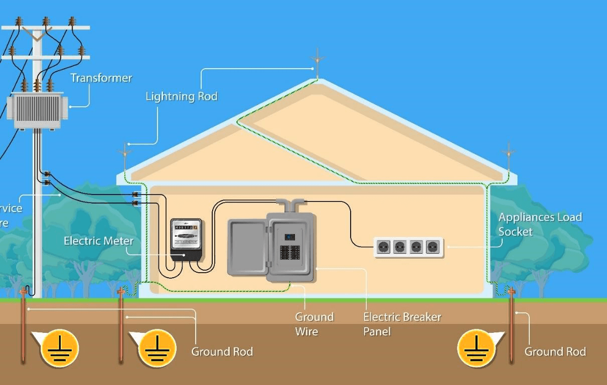
Figure 5 – House earthing system
Go back to the Contents Table ↑
2.1 TT System Directly Connected To the Earth
In this type of Earthing System, connection to the supply source is directly connected to the earth, denoted by the first T. The consumer has solidly earthed independently of the source earthing method, donated by the second T.
The neutral and earthing conductors must be separated through the installation because the power supply authority only provides the neutral or protective conductor for the connection to the consumer. This method is the standard arrangement for most installations fed from an overhead supply.
Figure 6 – TT Earthing System

Go back to the Contents Table ↑
2.2 TN-S System With Separate Ground & Neutral
In this system, the Ground Conductor & Neutral Conductor are separate throughout the distribution system. The protective conductor is the metallic covering of the cable supplying the installation.
All the exposed conductive parts of the installation are connected to this protective conductor or via the main earthing terminal of the installation. S indicates that the working neutral line and the protection line are strictly separated, so the PE line is called a dedicated protection line.
The customer may have an earth terminal connected to the sheath of the service cable or a separate earth conductor. Most installations with an underground supply will likely be of this type of earthing.
Figure 7 – TN-S earthing system

Go back to the Contents Table ↑
2.3 TN-C System With Combined Ground & Neutral
The Neutral and the protective earth are combined into a single conductor throughout the system. All the exposed and conductive parts of the installation are connected to the PEN conductor.
The third letter in this type of earthing, C, indicates that the working neutral and protection lines are one. Therefore, in TN-C (Terra Neutral – Combined) method, the earth and neutral share the same conductor (two-wire single-phase).
The neutral conductor is also a protective conductor referred to as a PEN (Protective Earth and Neutral) conductor.
Related electrical guides & articles


Mohammed Ayman
I earned my degree from Eastern Mediterranean University (Turkey, North Cyprus) in B.S Electrical & Electronic Engineering; shortly after, I began my career as an electrical site engineer in a mega-scale project in Qatar which allowed me to monitor and supervise electrical site installations. I indulged in the design field of the electrical low voltage distribution systems and have accomplished more than 10 projects with the compliance of the national codes & international standards.Profile: Mohammed Ayman
