
Estimated Study Time: 13 minutes
Substation Grounding
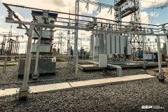
An electrical substation is a critical resource in a power system. Safe operation of a substation calls for a properly designed and installed grounding system. A well-designed grounding system will ensure reliable performance of the substation over its entire service life.
How does good grounding improve substation reliability?

Good grounding path of sufficiently low impedance ensures fast clearing of faults. A fault remaining in the system for long may cause several problems including those of power system stability. Faster clearing thus improves overall reliability. It also ensures safety.
This combination is essentially unsafe because any person coming into contact with the enclosure is exposed to higher potentials for a longer duration. Therefore, substation reliability and safety must be as ‘built-in’ as possible by good grounding scheme, which in turn will ensure faster fault clearing and low enclosure potential rise.
Ensuring Proper Grounding
The following steps, when put into practice, will ensure a reliable, safe and trouble-free substation grounding system:
- Size conductors for anticipated faults
- Use the right connections
- Ground rod selection
- Soil preparation
- Attention to step and touch potentials
- Grounding using building foundations **
- Grounding the substation fence **
- Special attention to operating points **
- Surge arrestors must be grounded properly **
- Grounding of cable trays **
- Temporary grounding of normally energized parts **
** Will be published in next part of this technical article
1. Size Conductors For Anticipated Faults
Conductors must be large enough to handle any anticipated faults without fusing (melting).
Failure to use proper fault time in design calculations creates a high risk of melted conductors. Two aspects govern the choice of conductor size: the first is the fault current that will flow through the conductor and the second is the time for which it can flow.
The fault current depends on the impedance of the ground fault loop. The time of current flow is decided by the setting of the protective relays/circuit-breaking devices, which will operate to clear the fault.
The IEEE 80 suggests using a time of 3.0 s for the design of small substations. This time is also equal to the short-time rating of most switchgear.
2. Use the Right Connections

It is very evident that the connections between conductors and the main grid and between the grid and ground rods are as important as the conductors themselves in maintaining a permanent low-resistance path to ground.
The basic issues here are:
- The type of bond used for the connection of the conductor in its run, with the ground grid and with the ground rod
- The temperature limits, which a joint can withstand.
Pressure-type connections produce a mechanical bond between conductor and connector by means of a tightened bolt-nut or by crimping using hydraulic or mechanical pressure. This connection either holds the conductors in place or squeezes them together, providing surface-to-surface contact with the exposed conductor strands.
On the other hand, the exothermic process fuses the conductor ends together to form a molecular bond between all strands of the conductor.
Temperature limits are stated in standards such as IEEE 80 and IEEE 837 for different types of joints based on the joint resistance normally obtainable with each type. Exceeding these temperatures during flow of fault currents may result in damage to the joint and cause the joint resistance to increase, which will result in further overheating.
The joint will ultimately fail and result in grounding system degradation or total loss of ground reference with disastrous results.
3. Ground Rod Selection

In MV and HV substations, where the source and load are connected through long overhead lines, it often happens that the ground fault current has no metallic path and has to flow through the groundmass (earth). This means that the ground rods of both source and load side substations have to carry this current to or from the groundmass.
The length, number and placement of ground rods affect the resistance of the path to earth. Doubling of ground rod length reduces resistance by a value of 45%, under uniform soil conditions. Usually, soil conditions are not uniform and it is vital to obtain accurate data by measuring ground rod resistance with appropriate instruments.
For maximum efficiency, grounding rods should be placed no closer together than the length of the rod. Normally, this is 10 ft (3 m). Each rod forms an electromagnetic shell around it, and when the rods are too close, the ground currents of the shells interfere with each other.
It should be noted that as the number of rods is increased, the reduction of ground resistance is not in inverse proportion. Twenty rods do not result in 1/20th of the resistance of a single rod but only reduce it by a factor of 1/10th.
For economic reasons, there is a limit to the maximum distance between rods.
Normally, this limit is taken as 6 m. At more than 6 m, the cost of additional conductor needed to connect the rods makes the design economically attractive.
In certain cases, the substation layout may not have the required space and acquiring the needed space may involve substantial expense. Four interconnected rods on 30 m centers will reduce resistivity 94% over one rod but require at least 120 m of conductor.
On the other hand, four rods placed 6 m apart will reduce resistivity 81% over one rod and use only 24 m of conductor.
4. Soil Preparation
Soil resistivity is an important consideration in substation grounding system design. The lower the resistivity, the easier it is to get a good ground resistance.
Areas of high soil resistivity and those with ground frost (which inturn causes the soil resistivityto increase by orders of magnitude) need special consideration. The highest ground resistivity during the annual weather cycle should form the basis of the design since the same soil will have much higher resistivity during dry weather when percentage of moisture in the ground becomes very low.

One approach to take care of this problem is to use deep driven ground rods so that they are in contact with the soil zone deep enough to remain unaffected by surface climate.
The other approach is to treat the soil around the ground rod with chemical substances that have the capacity to absorb atmospheric/soil moisture.
Use of chemical rods is one such solution.
5. Attention to Step and Touch Potentials
Limiting step and touch potential to safe values in a substation is vital to personnel safety.
Step potential is the voltage difference between a person’s feet and is caused by the voltage gradient in the soil at the point where a fault enters the earth. The potential gradient is steepest near the fault location and thereafter reduces gradually. Just 75 cm away from the entry point, voltage usually will have been reduced by 50%.
Thus at a point of 75 cm from the fault (which is less than the distance of a normal step), a fatal potential of a few kilovolts can exist.
Touch potential represents the same basic hazard, except the potential exists between the person’s hand and his or her feet. This happens when a person standing on the ground touches a structure of the substation, which is conducting the fault current into ground (for example, when an insulator fixed on a gantry flashes over, the gantry dissipates the current to earth).
Since the likely current path within the human body runs through the arm and heart region instead of through the lower extremities, the danger of injury or death is far greater in this case. For this reason, the safe limit of touch potential is usually much lower than that of step potential.
This mesh will have to be installed in the immediate vicinity of any switches or equipment a worker might touch, and connected to the main ground grid. Such an equipotential mesh will equalize the voltage along the worker’s path and between the equipment and his or her feet. With the voltage difference (potential) thus essentially eliminated, the safety of personnel is virtually guaranteed.
An equipotential wire mesh safety mat is usually fabricated from #6 or #8 AWG copper or copper-clad wire to form a 0.5 ×0.5 m or 0.5 ×1 m mesh. Many other mesh sizes are available.
To ensure continuity across the mesh, all wire crossings are brazed with a 35% silver alloy. Interconnections between sections of mesh and between the mesh and the main grounding grid should be made so as to provide a permanent low-resistance high-integrity connection.
To bi continued in part 2…
Resource: Practical Grounding, Bonding, Shielding and Surge Protection – G. Vijayaraghavan; Mark Brown; Malcolm Barnes (Get this book at Amazon)
Related electrical guides & articles


Edvard Csanyi
Hi, I'm an electrical engineer, programmer and founder of EEP - Electrical Engineering Portal. I worked twelve years at Schneider Electric in the position of technical support for low- and medium-voltage projects and the design of busbar trunking systems.I'm highly specialized in the design of LV/MV switchgear and low-voltage, high-power busbar trunking (<6300A) in substations, commercial buildings and industry facilities. I'm also a professional in AutoCAD programming.
Profile: Edvard Csanyi

Can you send me a typical Grounding Resistance Calculations Report. I need to do one to show that the resistance is <5 Ohm at a Storage tank terminal. my email is [email protected]. Thank you so much
Best Regards,
Ernest
Good morning sir, I really appreciate your help here in broading our mind set on substation ground systems, please suggest to me, the best way to achieve a better ground system for an area that was recovered and sandfilled with a sandy soil type.
Thank you for such a complete article.
I would say that in order to ensure an effective substation grounding, it is recommended to use exothermic welding instead of a mechanical one as it is a molecular bond with equal or higher conductivity than the conductors. I share with you some of the key differences between exothermic and mechanical welding. Hope you find it useful.
Hey, great article on the topic of substation grounding!
There is an Android app that does all the calculations for you, it is called Instaground. It checks your design for safety requirements and also does other grounding calculations.
Keep up the good work!
You are doing a great job. This is a great and am hoping to build up something like this or better. Any tips or guidance.
just i want alot of information about grounding of substation and as well as generation substation pleas attach afile related to this one with soft copy
I have to design earthing system for my substation ( 11kV/400 V 2 MVA). Unfortunately the building construction has been started and it is difficult to design a earthing system with mesh under the building. So are the other solutions to get safe touch and step potentials. Can I design a system like two rings of earthing wire around the perimeter of my substation (18m*9m) and rods in regular intervals. In this case how can I do the calculation?
With respect to your articles, I’ve learned a lot and I’ll do well on this articles. We are already suffering from a grounding system in substation in my company. Because of the rocky ground in our location.
your articles are been a wonderful source for industrial training report ,please i will need a literature review as well abstract on injection substation.