
Estimated Study Time: 8 minutes
Nodes, Branches, and Loops
Since the elements of an electric circuit can be interconnected in several ways, we need to understand some basic concepts of network topology. To differentiate between a circuit and a network, we may regard a network as an interconnection of elements or devices, whereas a circuit is a network providing one or more closed paths.
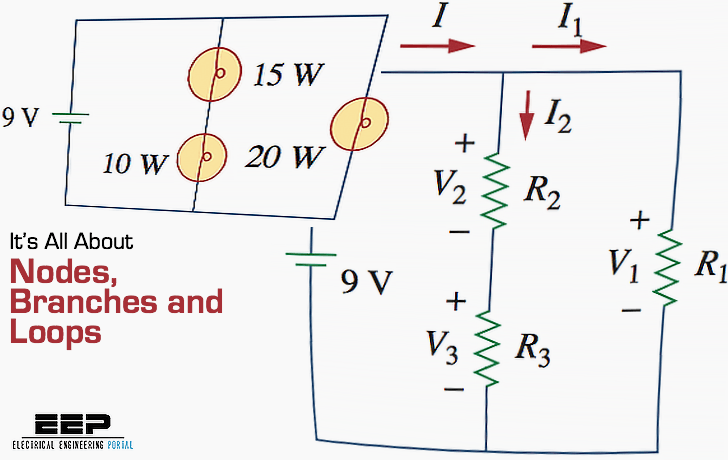 Electric Circuits? It’s All About Nodes, Branches, and Loops
The convention, when addressing network topology, is to use the word network rather than circuit. We do this even though the word network and circuit mean the same thing when used in this context.
In network topology, we study the properties relating to the placement of elements in the network and the geometric configuration of the network. It’s all about circuit elements such as branches, nodes, and loops.
Branches (Two-Terminal Elements)
A branch represents a single element such as a voltage source or a resistor. In other words, a branch represents any two-terminal element.
The circuit in Figure 1 has five branches, namely, the 10V voltage source, the 2A current source, and the three resistors.
Figure 1 – Nodes, branches, and loops

Nodes (Point of Connection)
A node is the point of connection between two or more branches.
A node is usually indicated by a dot in a circuit. If a short circuit (a connecting wire) connects two nodes, the two nodes constitute a single node. The circuit in Figure 1 has three nodes a, b, and c.
Notice that the three points that form node b are connected by perfectly conducting wires and therefore constitute a single point. The same is true of the four points forming node c. We demonstrate that the circuit in Fig. 1 has only three nodes by redrawing the circuit in Figure 2. The two circuits in Figures 1 and 2 are identical.
However, for the sake of clarity, nodes b and c are spread out with perfect conductors as in Figure 1.
Figure 2 – The three-node circuit of Figure 1 is redrawn

Loops (Closed Path in a Circuit)
A loop is any closed path in a circuit. A loop is a closed path formed by starting at a node, passing through a set of nodes, and returning to the starting node without passing through any node more than once. A loop is said to be independent if it contains at least one branch which is not a part of any other independent loop. Independent loops or paths result in independent sets of equations.
It is possible to form an independent set of loops where one of the loops does not contain such a branch. In Figure 2, abca with the 2Ω resistor is independent. A second loop with the 3Ω resistor and the current source is independent.
The third loop could be the one with the 2Ω resistor in parallel with the 3Ω resistor. This does form an independent set of loops.
A network with b branches, n nodes, and l independent loops will satisfy the fundamental theorem of network topology:
b = l + n – 1
As the next two definitions show, circuit topology is of great value to the study of voltages and currents in an electric circuit.
Two or more elements are in series if they exclusively share a single node and consequently carry the same current.
Two or more elements are in parallel if they are connected to the same two nodes and consequently have the same voltage across them.
Elements are in series when they are chain-connected or connected sequentially, end to end. For example, two elements are in series if they share one common node and no other element is connected to that common node. Elements in parallel are connected to the same pair of terminals.
In the circuit shown in Fig. 1, the voltage source and the 5Ω resistor are in series because the same current will flow through them. The 2Ω resistor, the 3Ω resistor, and the current source are in parallel because they are connected to the same two nodes b and c and consequently have the same voltage across them.
The 5Ω and 2Ω resistors are neither in series nor in parallel with each other.
Node Voltage Problems in Circuit Analysis (VIDEO)
Suggested Courses
The Essentials of Electricity and DC Circuit Analysis (Practice Problems Included)
This course covers the fundamental ideas of electrical direct current (DC) circuits (Ohm’s Law, Kirchhoff’s Laws, Series and Parallel Circuits, and so on), as well as the most common practice problems that students encounter while learning.
The course consists of 12 sections and lasts 4 hours and 40 minutes in total.
The Essentials of Electricity and DC Circuit Analysis (Practice Problems Included)
Practice Problems for DC Branch-Current Analysis
This course addresses twelve circuit problems and their solutions, concentrating on DC series-parallel networks. This problem set has been developed at the students’ request to facilitate the practice of concepts shown in the DC circuit analysis courses accessible for streaming on this site.
This course serves as a supplementary resource to the “Basic Fundamentals of Electricity and DC Circuit Analysis” course available on EEP Academy.
After the problem is addressed or attempted, the learner may resume the video to observe the instructor’s solution.
Reference: Fundamentals of Electric Circuits by Charles K. Alexander and Matthew N. O. Sadiku
Related electrical guides & articles


Edvard Csanyi
Hi, I'm an electrical engineer, programmer and founder of EEP - Electrical Engineering Portal. I worked twelve years at Schneider Electric in the position of technical support for low- and medium-voltage projects and the design of busbar trunking systems.I'm highly specialized in the design of LV/MV switchgear and low-voltage, high-power busbar trunking (<6300A) in substations, commercial buildings and industry facilities. I'm also a professional in AutoCAD programming.
Profile: Edvard Csanyi

what are dependent and independent branches?i cant find it
i am a toyheeb ahmed chowdhary .iam a sdtudent of eng of branch of electrical
i know i.e very good idea to proved the study is the very easy way to solve so i like it your idea
A branch may consists more than one element – is it true !!!
A branch is considered as any two terminals element in a circuit.
Yes a branch may consist of more than 1 elements,a simple case is of having more than 1 LED in a series connection.
This is all wrong!!!
Note that the formula b=l+n-1 is not satisfied for Figure 1 if we use the definitions given in this text. The number of independent loops is clearly 3. The number of nodes is 4 (and NOT 3 as stated in the text!! Point A is NOT a node!!).So l+n-1=6. It is said that for that figure, b=5. which is not the number of branches.
The problem is that the definition of branches given here is not what is used in network topology. If we use the definition given here, the formula b=l+n-1 could not work. This is obvious since we can increase the number of, say, resistors in a section (increasing the number of branches according to the definition given here) while keeping the number of independent loops and nodes constant. Therefore the formula b=l+n-1 cannot work with the definition of branches given here.
A branch in network topology is defined as a segment connecting two nodes. In Figure 1, there are thus 6 branches. With this definition, the formula b=n+l-1 works.
For Figure 2, b=4, l=3,n=2.
It’s incredible that nodes and branches are incorrectly explained!
Hi Patrik,
So in any Resistor network if one resistor’s end is connected to a node and the other is open, then will it be counted in Branch or not?
“A node is the point of connection between two or more branches.”
This phrase is wrong. A node is the point of connection between THREE or more branches. If you disagree please provide an example where 2 branches connect and form a node in that point.
Point of connection of 3 or more branches is junction. Thank you.
Would nodes B and C also be considered junctions?
And is junction a term not used with Kirchoff computations as the term node is?
branch is an element; two elements connected to one point makes that point node:
A branch is a SEPARATE lead distributed from a TRUNK. “Two or more branches” distributed from a trunk are a NODE. A TRUNK must be present to facilitate a BRANCH, therefore “Two or more BRANCHES” lead from the trunk. A junction of two or more branches will lead three directions since a trunk must be present. Because the “Trunk” is never mentioned does not mean it does not exist. It must exist for a branch to exist. “DDDDDDUUUUUUHHHHHH! I have a brain somewhere, and my name is Purple”.
There are two types of nodes, A simple node is connecting 2 elements, more than 2 elements connection is called as Principal node.
Can you please give simple definitions of simple physics
You would not understand. It would be too simple for you.
What to more about powerbank thing how is it done and all its connection.otherwise plse thinks
How we solve simple circuit by using kcl in which all currents are given with any known votage to find any one current in circuit?