
Estimated Study Time: 9 minutes
Principles of shock protection
Protection of persons and livestock against electric shock is a fundamental principle in the design of electrical installations in accordance with BS 7671: Requirements for Electrical Installations, commonly known as The IEE Wiring Regulations. Use of the correct earthing system is an essential part of this process.
 The essentials of electric shock protection, earthing systems and RCDs
Electric shock may arise from direct contact with live parts, for example when a person touches a live conductor that has become exposed as a result of damage to the insulation of an electric cable.
Alternatively it may arise from indirect contact if, for example, a fault results in the exposed metalwork of an electrical appliance, or even other metalwork such as a sink or plumbing system becoming live.
In either case there is a risk of an electric current flowing to earth through the body of any person who touches the live conductor or live metalwork. (See Figure 1).

Fuses and circuit-breakers provide the first line of defence against indirect contact electric shock. If the installation is correctly earthed (i.e. all the exposed metalwork is connected together and to the main earth terminal of the installation) then an indirect contact fault will cause a very high current to flow to earth through the exposed metalwork.
This will be sufficient to ‘blow’ the fuse or trip the circuit-breaker, disconnecting that part of the installation within the time specified in BS 7671 and so protecting the user.
They also provide protection against indirect contact under certain installation conditions where fuses and circuit-breakers cannot achieve the desired effect, for example where the earthing systems described above are ineffective.
Earthing Systems
For a full understanding of electric shock protection it is necessary to consider the different types of earthing system in use. BS 7671 lists five types as described below:
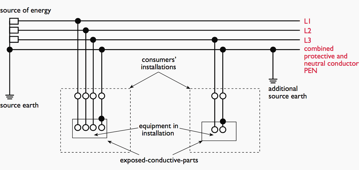
TN-C System
In this arrangement a single protective earth and neutral (PEN) conductor is used for both the neutral and protective functions, all exposed-conductive-parts being connected to the PEN conductor. It should be noted that in this system an RCD is not permitted since the earth and neutral currents cannot be separated.
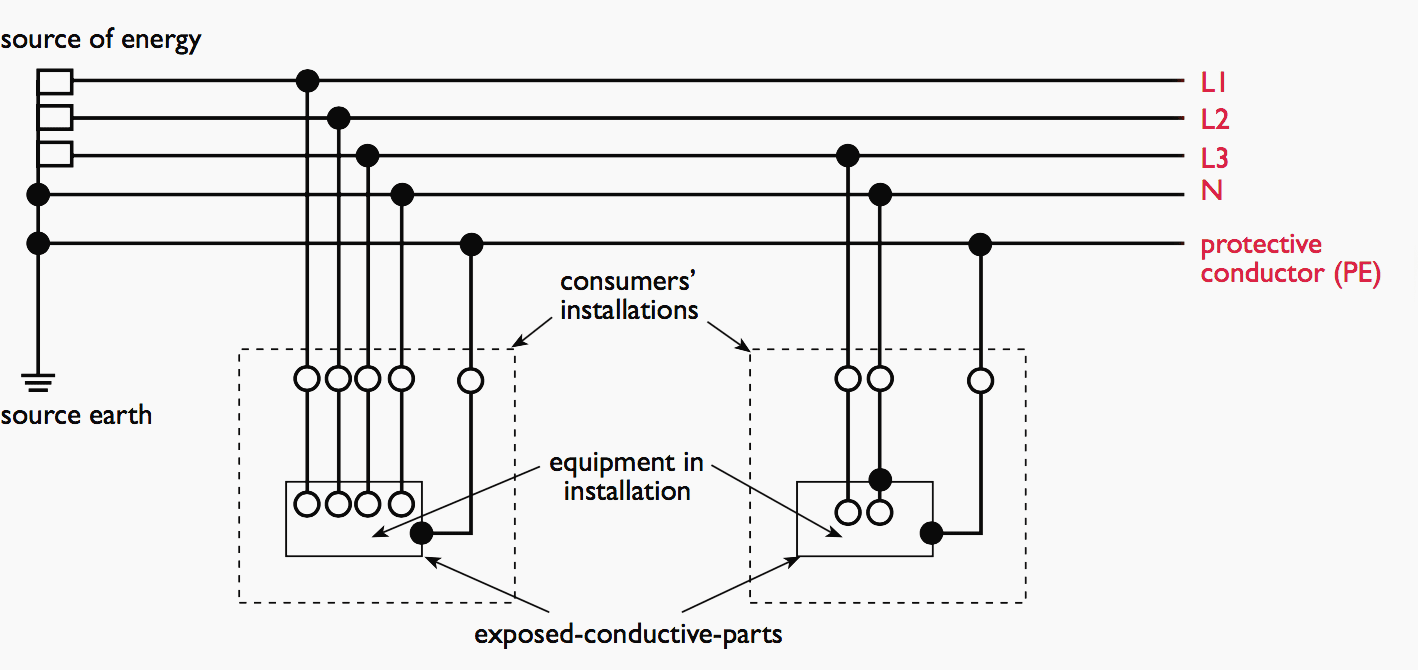
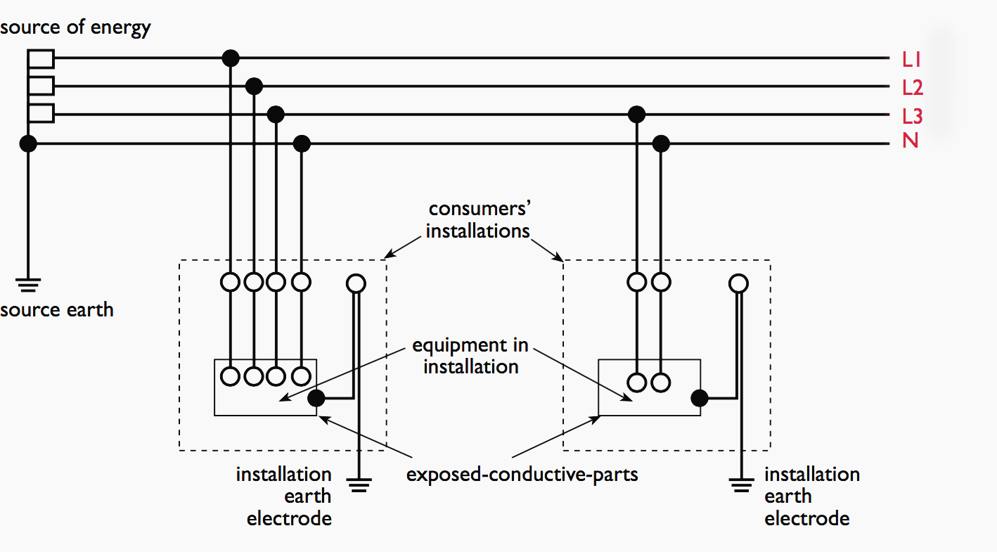
TN-S System
With this system the conductors for neutral and protective earth (PE) circuits are separate and all exposed conductive-parts are connected to the PE conductor. This system is the one most commonly used in the UK, although greater use is being made of the TN-C-S arrangement due to the difficulties of obtaining a good substation earth.
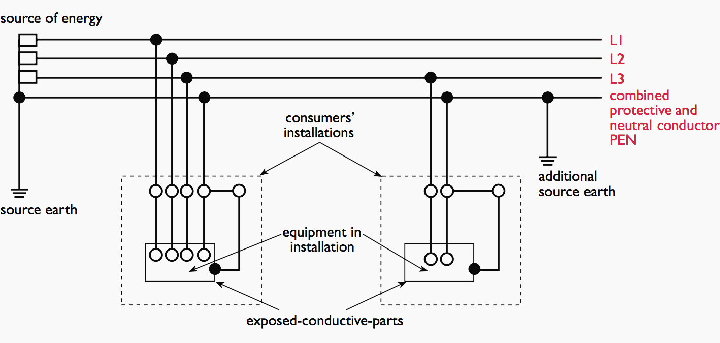
TN-C-S System
The usual form of a TN-C-S system is where the supply is TN-C and the arrangement of the conductors in the installation is TN-S. This system is often described as a protective multiple earthing (PME) system.
This is incorrect since PME is a method of earthing.
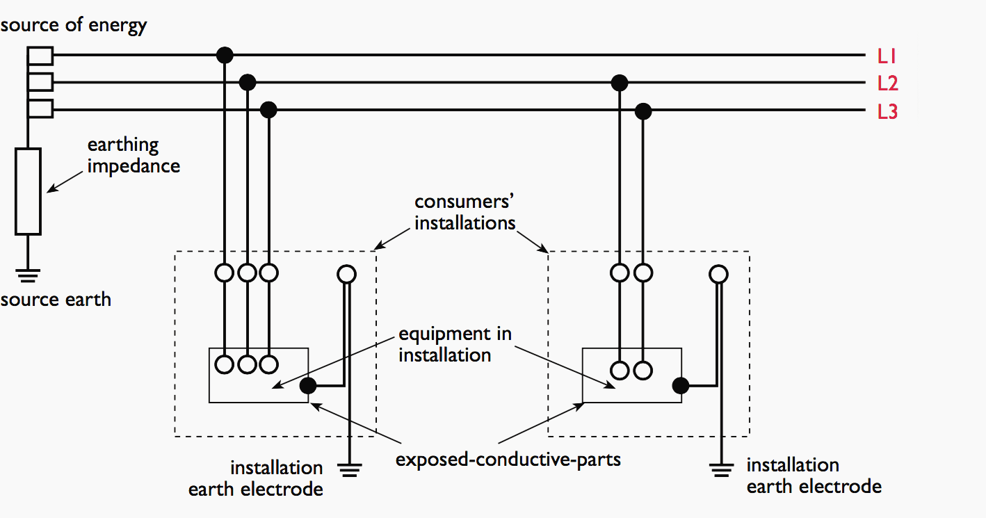
TT System
In a TT system the electricity supply provider and the consumer must both provide earth electrodes at appropriate locations, the two being electrically separate. All exposed conductive-parts of the installation are connected to the consumer’s earth electrode.
IT System
Unlike the previous systems, the IT system is not permitted, except under special licence, for the low voltage supply in the UK. It does not rely on earthing for safety, until after the occurrence of a first-fault, as the supply side is either completely isolated from earth or is earthed through a high impedance.
Protection Against Direct and Indirect Contact
When considering protection against electric shock, it is necessary to understand the difference between ‘direct contact’ and ‘indirect contact’.
Direct contact electric shock is the result of simultaneous contact by persons or livestock with a normally live part and earth potential. As a result the victim will experience nearly full mains voltage across those parts of the body which are between the points of contact.
Indirect contact electric shock results from contact with an exposed conductive part made live by a fault condition and simultaneous contact with earth potential. This is usually at a lower voltage.
Protection against direct contact electric shock is based on normal common sense measures such as insulation of live parts, use of barriers or enclosures, protection by obstacles or protection by placing live parts out of reach. As a result, under normal conditions it is not possible to touch the live parts of the installation or equipment inadvertently.
Protection against indirect contact electric shock is slightly more complicated hence a number of options are given in BS 7671 for the installation designer to consider.
The majority of these require specialist knowledge or supervision to be applied effectively. The most practical method for general use is a combination of protective earthing, protective equipotential bonding and automatic disconnection of supply.
RCD Selection Guides
The following selection guides are intended to help the specifier or installer decide on the most appropriate solution to common installation arrangements.
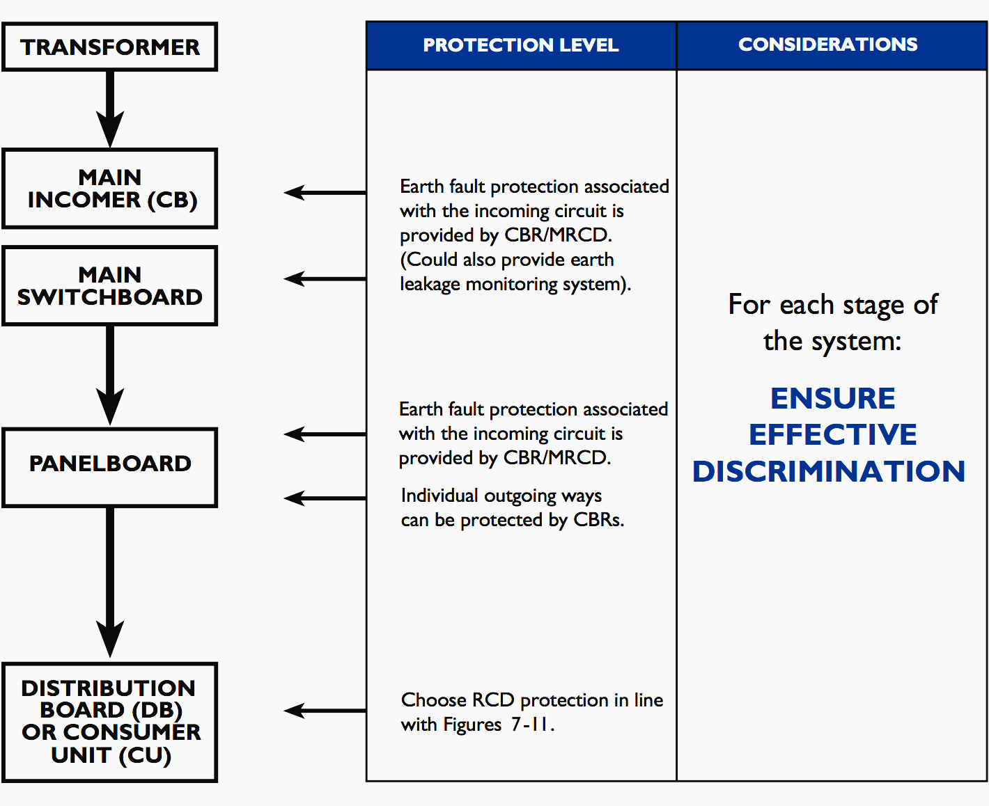
Commercial/industrial system RCD protection options
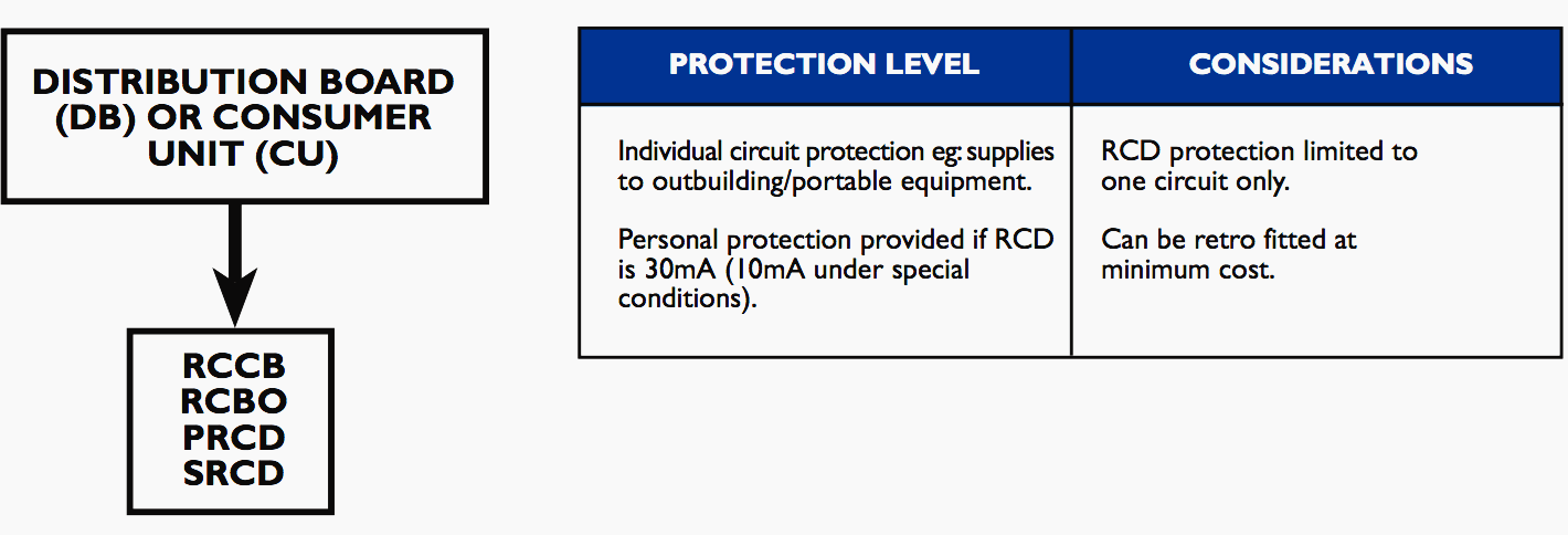
Sub distribution and final circuit RCD protection options
Outgoing circuit RCD protection, separate from the distribution board
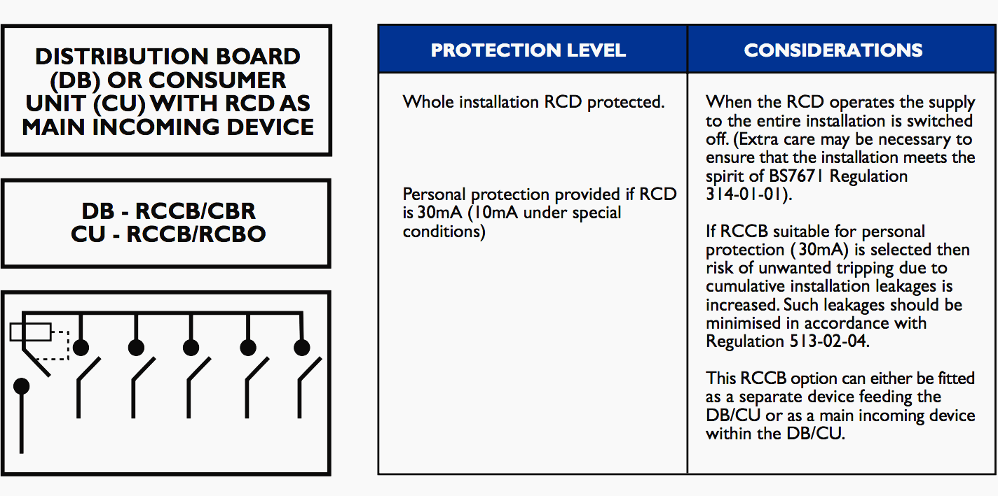
Whole installation protection
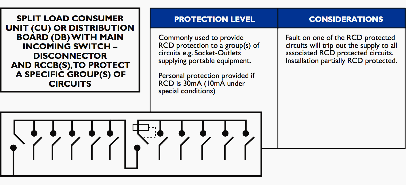
Split load protection (A)
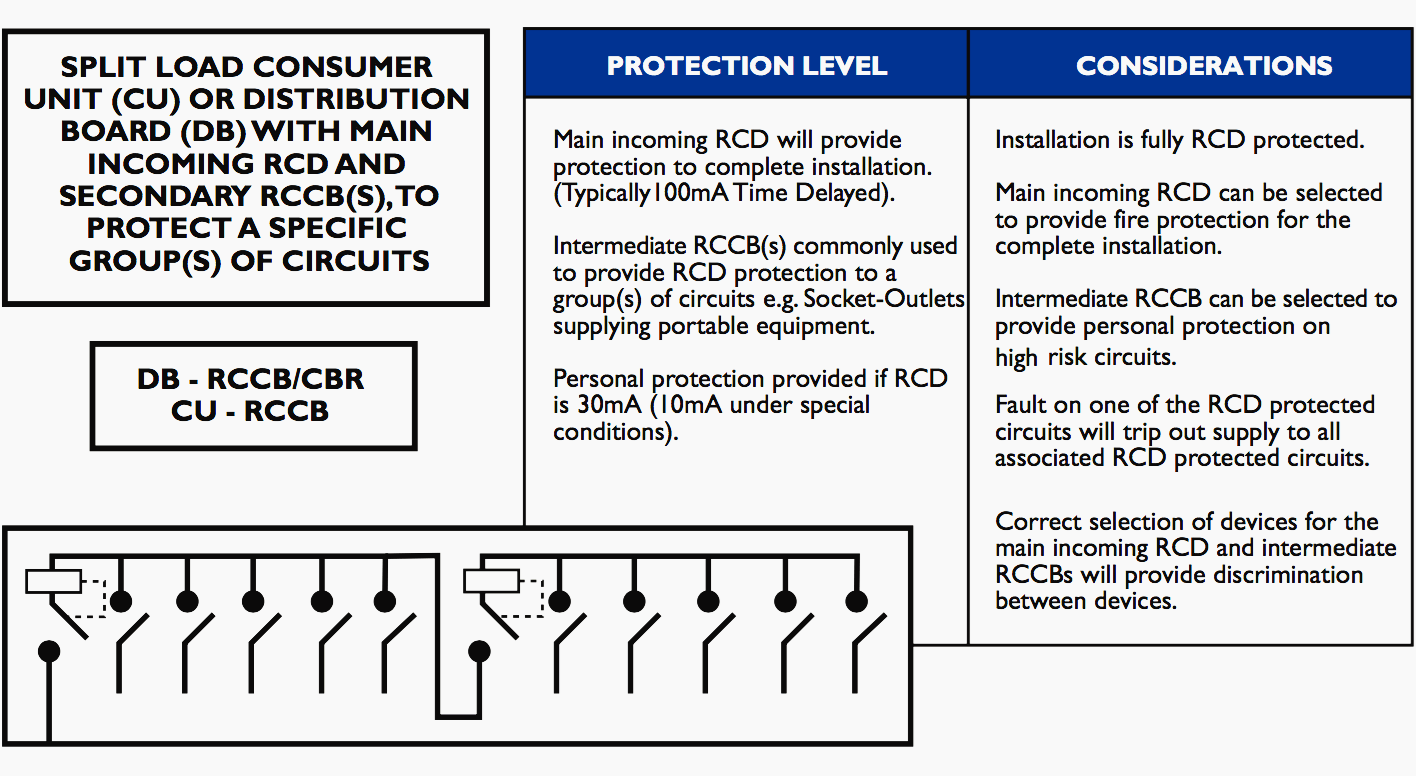
Split load protection (B)
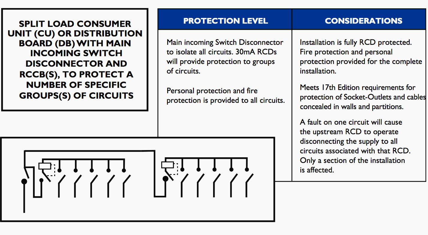
Dual Split load protection (C)
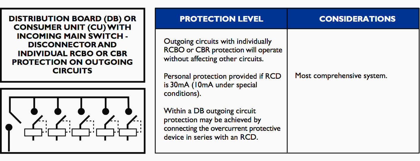
The most comprehensive option – individual outgoing protection on all ways
Reference // The RCD Handbook by BEAMA
Related electrical guides & articles


Edvard Csanyi
Hi, I'm an electrical engineer, programmer and founder of EEP - Electrical Engineering Portal. I worked twelve years at Schneider Electric in the position of technical support for low- and medium-voltage projects and the design of busbar trunking systems.I'm highly specialized in the design of LV/MV switchgear and low-voltage, high-power busbar trunking (<6300A) in substations, commercial buildings and industry facilities. I'm also a professional in AutoCAD programming.
Profile: Edvard Csanyi

The figure for tn-s shows the pen wire connected to the earth of the equipment in the single phase example. This varies from fig v.1 in iec 60950-1, and is not permitted in Australia where the pen is not allowed to connect to accessible metal parts. At the very least it’d generate earth loops via different earth potentials if not equipotentially bonded.
Edvard,
A comment on the final option (an RCBO for each sub-circuit; fig. 12): This often doesn’t provide the discrimination (or ‘selectivity’) that it appears to do – and that BS 7671 & similar standards require. The problem is that RCBOs for final sub-circuits are normally single-pole devices i.e. when tripped they break only the phase conductor but not the neutral.
Suppose that somewhere in the installation there’s a neutral-to-earth short. It could be inside an appliance, and so long as that appliance remains plugged in, the fault exists, producing an unsuspected connection between the neutral & earth bar. In the usual D.B. or consumer unit, all sub-circuits share the same neutral bar.
Therefore a healthy appliance on a completely different sub-circuit will create a current divided between the neutral and earth, by courtesy of the stray connection in the faulty appliance. The problem is reduced if every socket has a double-pole switch, but many don’t – and even where they do, who’s to say if the faulty appliance has been switched off?
In any case, switches in lighting circuits are normally only single-pole, so any of these would produce a significant unbalanced current. We could expect some or all of the RCBOs to trip, depending which ones were supplying current, (and puzzling the user!). Localizing the fault could become a skilled job.)
Regards, David Renshaw.