
Estimated Study Time: 12 minutes
Electrical braking of 3-phase motor
In many industrial systems, motors are stopped simply by natural deceleration. The time this takes depends solely on the inertia and resistive torque of the machine the motor drives. However, the time often needs to be cut down and electrical braking is a simple and efficient solution.
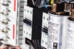
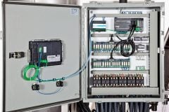
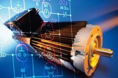
 Electrical Braking Of Asynchronous Motors - The Guidelines (photo credit: Chris Shontz via Flickr)
Compared to mechanical and hydraulic braking systems, it has the advantage of steadiness and does not require any wear parts.
Electrical braking options covered in this article //
- Countercurrent braking
- Braking by injection of DC current
- Electronic braking
- Braking by oversynchronous operation
- Other electrical braking systems
1. Countercurrent braking – The principle
The motor is isolated from the mains power while it is still running and then reconnected to it the other way round. This is a very efficient braking system with a torque, usually higher than the starting torque, which must be stopped early enough to prevent the motor starting in the opposite direction.
Several automatic devices are used to control stopping as soon as the speed is nearly zero:
- Friction stop detectors, centrifugal stop detectors,
- Chronometric devices,
- Frequency measurement or rotor voltage relays (slip ring motors), etc.
1.1 Squirrel cage motor
Before choosing this system (Figure 1), it is crucial to ensure that the motor can withstand countercurrent braking with the duty required of it. Apart from mechanical stress, this process subjects the rotor to high thermal stress, since the energy released in every braking operation (slip energy from the mains and kinetic energy) is dissipated in the cage.
Thermal stress in braking is three times more than in speed-gathering.
When braking, the current and torque peaks are noticeably higher than those produced by starting.
To brake smoothly, a resistor is often placed in series with each stator phase when switching to countercurrent. This reduces the torque and current, as in stator starting. The drawbacks of countercurrent braking in squirrel cage motors are so great that this system is only used for some purposes with low-powered motors.
1.2 Slip ring motor
To limit the current and torque peak, before the stator is switched to countercurrent, it is crucial to reinsert the rotor resistors used for starting, and often to add an extra braking section (see Figure 2).

With the right rotor resistor, it is easy to adjust the braking torque to the requisite value. When the current is switched, the rotor voltage is practically twice what it is when the rotor is at a standstill, which sometimes requires specific insulation precautions to be taken.
The motor can be brought to a standstill automatically by one of the above-mentioned devices, or by a voltage or frequency relay in the rotor circuit. With this system, a driving load can be held at moderate speed. The characteristic is very unstable (wide variations in speed against small variations in torque).
Go back to Electrical Braking Options ↑
2. Braking by injection of DC current
This electrical braking system is used on slip ring and squirrel cage motors (see Figure 3). Compared to the countercurrent system, the price of the source of rectified current is offset by fewer resistors. With electronic speed controllers and starters, this braking option does not add to the cost.
The process involves isolating the stator from the mains and sending rectified current to it. The rectified current creates a fixed flux in the air gap of the motor. For the value of this flux to ensure adequate braking, the current must be about 1.3 times greater than the rated current.
The surplus of thermal losses caused by this slight overcurrent is usually offset by a pause after braking.

As the value of the current is set by stator winding resistance alone, the voltage at the source of the rectified current is low. The source is usually provided by rectifiers or by speed controllers. These must be able to withstand transient voltage surges produced by the windings that have just been disconnected from the alternating supply (e.g. 380V RMS).
The movement of the rotor is a slip in relation to a field fixed in space (whereas the field spins in the opposite direction in the countercurrent system). The motor behaves like a synchronous generator discharging in the rotor.
Compared to a countercurrent system //
There are important differences in the characteristics obtained with a rectified current injection compared to a countercurrent system:
- Less energy is dissipated in the rotor resistors or the cage. It is only equivalent to the mechanical energy given off by masses in movement. The only power taken from the mains is for stator energising,
- If the load is not a driving load, the motor does not start in the opposite direction,
- If the load is a driving load, the system brakes constantly and holds the load at low speed. This is slackening braking rather than braking to a standstill. The characteristic is much more stable than in countercurrent.
With slip ring motors, the speed-torque characteristics depend on the choice of resistors.
With squirrel cage motors, the system makes it easy to adjust the braking torque by acting on the energising direct current. However, the braking torque will be low when the motor runs at high speed.
To prevent superfluous overheating, there must be a device to cut off the current in the stator when braking is over.
Go back to Electrical Braking Options ↑
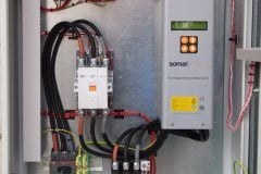
3. Electronic braking
Electronic braking is achieved simply with a speed controller fitted with a braking resistor. The asynchronous motor then acts as a generator and the mechanical energy is dissipated in the baking resistor without increasing losses in the motor.
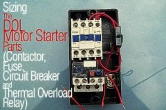
A motor starter unit has four basic functions:
- Isolating the load from the main circuit,
- Help protect the motor against short-circuits,
- Help protect the motor against thermal overload,
- Commutation or control (start – stop).
Each motor starter unit can be enhanced with additional functions depending on its purpose. These can include:
- Power: speed controller, soft starter, phase reversal, etc,
- Control: auxiliary contacts, time-delay, communication, etc.
According to the structure of a motor starter unit, the functions can be distributed in different ways. (see Figure 4) shows the possible arrangements.
Read more about the most common LV/MV motor starting devices //
Go back to Electrical Braking Options ↑
4. Braking by oversynchronous operation
This is where a motor’s load drives it above its synchronous speed, making it act like an asynchronous generator and develop a braking torque. Apart from a few losses, the energy is recovered by the mains supply. With a hoisting motor, this type of operation corresponds to the descent of the load at the rated speed. The braking torque exactly balances out the torque from the load and, instead of slackening the speed, runs the motor at constant speed.
On a slip ring motor, all or part of the rotor resistors must be short-circuited to prevent the motor being driven far above its rated speed, which would be mechanically hazardous.
This system has the ideal features for restraining a driving load:
- The speed is stable and practically independent of the driving torque,
- The energy is recovered and restored to the mains.
Go back to Electrical Braking Options ↑
5. Other electrical braking systems
Single-phase braking can still sometimes be found. This involves powering the motor between two mains phases and linking the unoccupied terminal to one of the other two connected to the mains.
Another system is braking by eddy current slackening. This works on a principle similar to that used in industrial vehicles in addition to mechanical braking (electric speed reducers). The mechanical energy is dissipated in the speed reducer. Braking is controlled simply by an excitation winding. A drawback however is that inertia is greatly increased.
Reversing //
3-phase asynchronous motors (see Figure 5) are put into reverse by the simple expedient of crossing two windings to reverse the rotating field in the motor.

The motor is usually put into reverse when at a standstill. Otherwise, reversing the phases will give countercurrent braking (see the paragraph on the Slip ring motor). The other electrical braking systems described above can also be used.
Single-phase motor reversing is another possibility if all the windings can be accessed.
Go back to Electrical Braking Options ↑
Reference // Automation Solution Guide – Schneider Electric
Related electrical guides & articles


Edvard Csanyi
Hi, I'm an electrical engineer, programmer and founder of EEP - Electrical Engineering Portal. I worked twelve years at Schneider Electric in the position of technical support for low- and medium-voltage projects and the design of busbar trunking systems.I'm highly specialized in the design of LV/MV switchgear and low-voltage, high-power busbar trunking (<6300A) in substations, commercial buildings and industry facilities. I'm also a professional in AutoCAD programming.
Profile: Edvard Csanyi

Dear Sir
What is the simplest configuration braking resistor for 3 Phase Motor?
Thank you.
sir,
can i get more information about “4. Braking by oversynchronous operation”.
Many thanks for all interesting articles and wishing you a happy new year Edvard.
Any idea about the possibility of using the energy at breaking to charge a battery? is this possible for an Asynchronous motor?
Regards.