
Electrical Design Tour Of a Datacenter
This technical article provides a top-to-bottom overview of Sun Microsystems’s Santa Clara, California datacenter from electrical design aspect. Sun’s electrical design tour of Santa Clara datacenter is done through a series of single line diagrams. These diagrams illustrate the various components and how they are connected without the detail of showing each wire for each phase – hence the term single line diagram (SLD).
 Electrical Design of Sun's Datacenter In Santa Clara, California (photo credit: glumac.com)
Let’s start with the following topics:
- Electrical Yard
- Backup Generators
- Battery-Based UPS
- Pod Power Distribution
- Metering and Power Management
1. Electrical Yard
Sun’s Santa Clara project is one of the largest datacenter consolidation efforts in their recent history. It allowed them to construct an entirely new electrical service yard to supply power to new datacenters and buildings.
This electrical yard receives two 12 kV power feeds from Silicon Valley Power, each of which allows us to draw 4.5 MVA of continuous power. To ensure that Sun has the power to grow over time, they have negotiated with the local utility to provide up to 24 MW of additional power to the electrical yard through additional 4.5 MVA feeders.
A set of medium voltage switchgear allows the additional feeds to be incorporated into the electrical yard without disrupting existing service. The medium voltage switchgear feeds three similar sets of 480V switchgear through step-down transformers, one of which is illustrated in Figure 1.
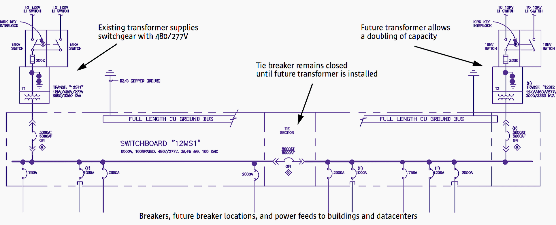
The switchgear supplies 480V power to office buildings and datacenters on the Santa Clara campus. The switchgear includes breakers for existing spaces and for future expansion, with conduit runs already installed to the future spaces.
Sun accommodates expansion at this level of the distribution hierarchy by supporting each of the three sets of switchgear with a single transformer. Each set of switchgear is configured with two halves that are connected with a tie breaker that is currently closed.
Visual Perspective Of Datacenter
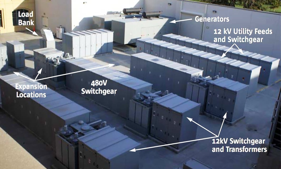
A photo of the Santa Clara switch yard gives a visual perspective (Figure 2 below).
In the foreground we can see three rows of similar switchgear. From right to left is the 12kV switching upstream of the transformer. Next is the transformer, followed by the 480V switchgear. Note the empty space at the end of two of the rows to accommodate an additional transformer and switchgear. One already has been installed.
Behind the 480V switchgear is the medium voltage, 12kV switchgear that accommodates existing and future utility feeds. Also visible in the photo are two diesel backup generators.
Go back to Go back to Design Topics ↑
2. Backup Generators
Because the majority of Sun’s datacenters are for research and development efforts, the pods in them are designed to Tier 1–2 specifications. For 20 percent of the load, Sun deploys UPS to support more critical operations.
As operational risks increase, Sun deploys generators behind the UPS to provide continuous power.
The generators provide power to a set of paralleling switchgear that combines the generator outputs. A 1000 kW load bank is installed to provide a full load when testing the generators. Regular 100 percent load testing of generators is important to make sure the generators are operating correctly and always ready to accept load.
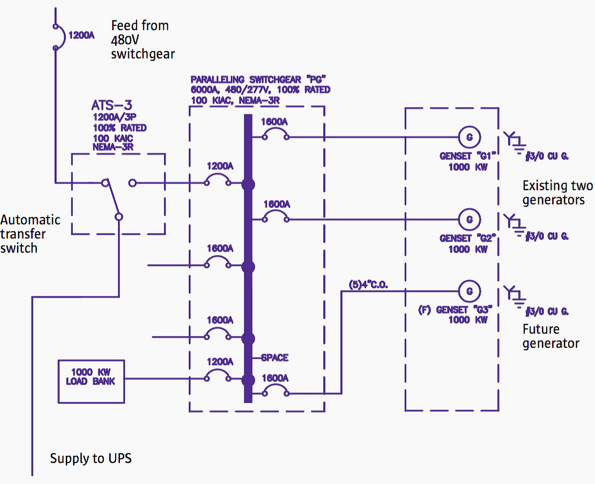
The paralleling switchgear currently feeds one 800 kVA UPS with provisions for future growth.
In the event of a failure, the feed is switched through automatic transfer switches (ATS). Two automatic transfer switches (ATS) switch the power feed for the UPS from utility power to generator power in the event of a power failure. A third ATS supplies power to keep the cooling system operating.
Go back to Go back to Design Topics ↑
3. Battery-Based UPS
Sun’s Santa Clara site is equipped to accommodate a fourth UPS to bring the total to 3.2 MVA. The site uses three 800 kVA UPS capable of providing up to 2.4 MVA of uninterruptible power. Sun chose APC Symmetra MW units for the Santa Clara site for their modularity and efficiency.
The APC UPS is unique in that it enables the UPS system to grow in 200 kW increments.
At the Santa Clara site, two of the three UPS are sized with 800 kW frames with only 400 kW of power modules installed, right sizing the UPS to Sun’s day one needs. As their loads grow, Sun will add additional power modules that grow the UPS to its full 800 kW capacity with only minimal construction in the UPS room to match battery capacity to UPS capacity.
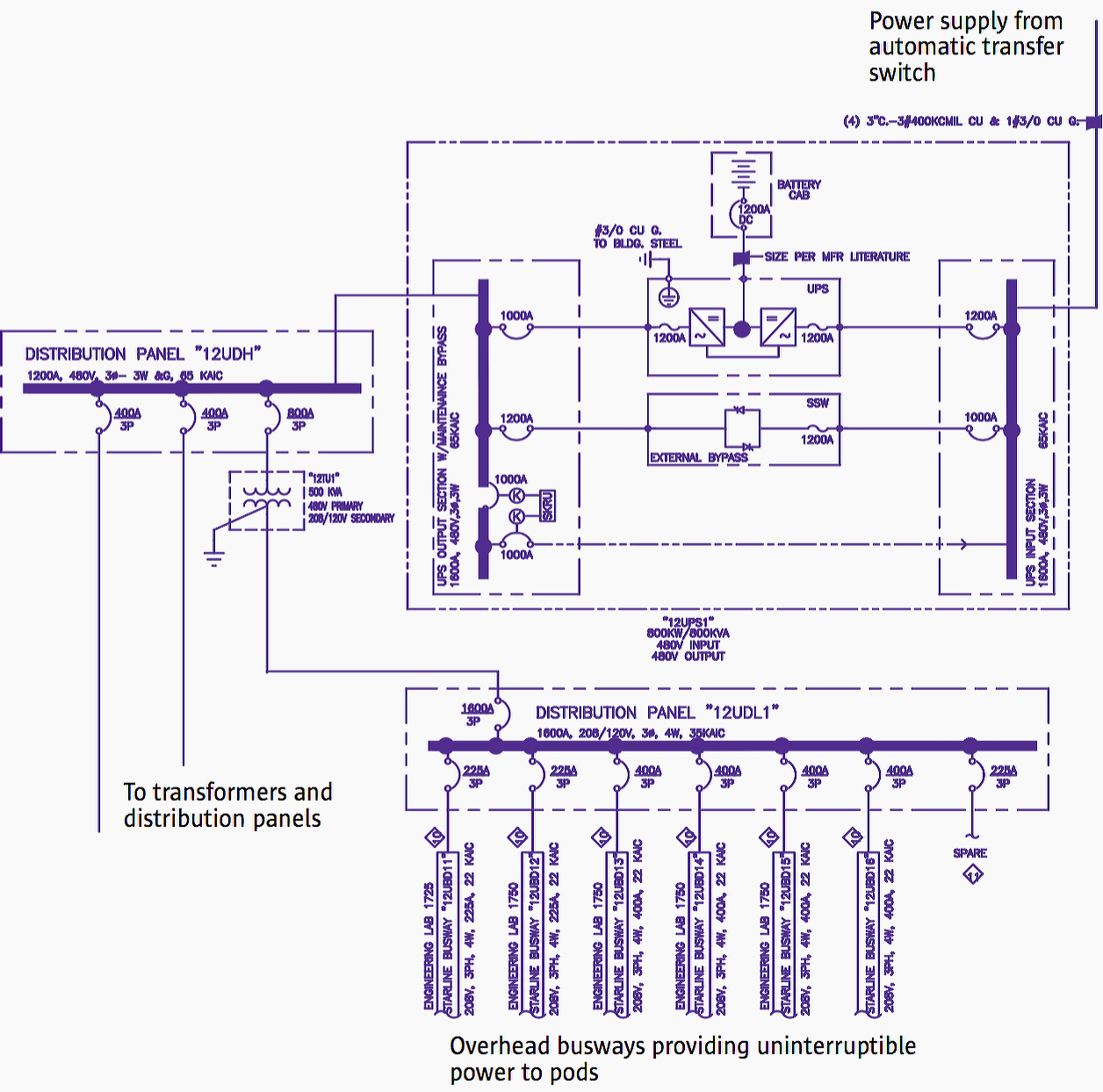
The UPS illustrated in Figure 4 takes its input power from the automatic transfer switch illustrated in Figure 15. Its output feeds a distribution panel that connects to three transformers that step down the 480/277V power to the 208/120V power that feeds the busways.
One transformer is illustrated in Figure 4. It supplies power to a distribution panel that feeds a set of 225A and 400A busways inside the datacenter spaces.
Go back to Go back to Design Topics ↑
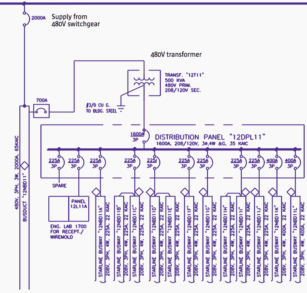
4. Pod Power Distribution
For the majority of pods that only require Tier 1 service, a single 480V feed from the switchgear supports multiple transformers that bring the voltage down to the 208/120V supplied to pods. The example shown in Figure 5 illustrates pairs of busway jumpered together.
Go back to Go back to Design Topics ↑
5. Metering and Power Management
One of the most important aspects of datacenter electrical design is an integrated metering and energy management system. These systems are critical because they provide the ability to evaluate how power is being used in the datacenter, power quality or disturbance events, how efficiently the datacenter is operating, and what impact any energy-saving measures have on overall efficiency.
As we know, the power usage effectiveness (PUE) is the ratio of total facility power to the IT equipment load.
In order to obtain this ratio, and to be able to observe energy consumption of the various datacenter subsystems, appropriate metering capabilities must be placed at strategic locations cascaded through the electrical system.
Metering Locations
In Sun’s Santa Clara datacenters, there is metering and power management in place at the following locations:
- The utility switchgear
- All major switchgear
- All UPS, ATS and generators
- Each overhead busway
- Each rack is equipped with a rack-mounted power distribution unit (rPDU) that monitors overall power consumption and also provides remote on/off per-outlet control. These rPDUs can be monitored over the network, providing fine-grained data on IT equipment loads.
Go back to Go back to Design Topics ↑
Reference // Electrical Design Of Energy Efficient Datacenters – Michael Ryan, Brett Rucker, Dean Nelson, Petr Vlasaty, Ramesh KV, Serena DeVito, and Brian Day Sun Global Lab and Datacenter Design Services


nice layout and article . thanks
Thanks. I learnt a lot from this article.
3.3.18:SAT
EEP
You are aware, at site AC HV testing of HV/EHV apparatus would be bit difficult
As transporting AC test set to site would be demanding.
However, it is seen, site testing of AC HV Cable & termination is done with DC HV test
[set available in test van].
Since such DC HV test van is anyway required at site for cables, it would be convenient to HV test the other
Apparatus also at DC. E.g. Power transformer, HV Switchgear, CT,VT ,Bus duct, Isolator Bus bars etc.
The above is never done by DC HV testing .
It is seen, other apparatus manufacturers would not allow their equipment to be DC HV tested, stating that
IEC & other standards do not specify the same. Needless to say, they do allow 5KV, 10KV DC Megger testing for IR tests.
Please opine on the above giving some elaboration.
If you have any query, please ask us.
WBR,
SHAM KANITKAR
94225 00471
NSK ENGG CORP
PUNE
INDIA
Well explainned article. I a would expected find eléctrical room with Air Conditioner .
Could you give more info about the outdoors 480v swithgear ?
Very good article, well presented.
Thank you David.