
Estimated Study Time: 23 minutes
Healthcare Facilities
Due to the critical nature of the care being provided at healthcare facilities and their increasing dependence on electrical equipment for preservation of life, they have special requirements for the design of their electrical distribution systems.
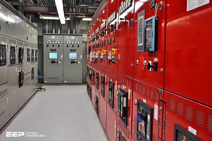 Electrical design of healthcare facilities (essential system requirements) - on photo: Power substation in St. Paul's Hospital; source: Status Electrical Corporation
Healthcare facilities are defined by NFPA (National Fire Protection Agency) as “Buildings or portions of buildings in which medical, dental, psychiatric, nursing, obstetrical, or surgical care are provided”.
These requirements are typically much more stringent than commercial or industrial facilities.
There are several agencies and organizations that develop requirements for healthcare electrical distribution system design. The following is a listing of some of the specific NFPA (National Fire Protection Agency) standards that affect healthcare facility design and implementation:
- NFPA 37-2015 – Standard for Stationary Combustion Engines and Gas Turbines
- NFPA 70-2014 – National Electrical Code
- NFPA 99-2015 – Healthcare Facilities
- NFPA 101-2015 – Life Safety Code
- NFPA 110-2016 – Standard for Emergency and Standby Power Systems
- NFPA 111-2016 – Standard on Stored Electrical Energy Emergency and Standby Power Systems
These standards and guidelines represent the most industry recognized requirements for healthcare electrical design.
However, the electrical design engineer should consult with the authorities having jurisdiction over the local region for specific electrical distribution requirements.
- Healthcare Electrical System Requirements
- Type 1 Essential Electrical Systems (EES)
- Paralleling Emergency Generators
1. Healthcare Electrical System Requirements
Healthcare electrical systems usually consist of two parts:
- Non-essential (or normal) electrical system.
- Essential electrical system.
All electrical power in a healthcare facility is important, though some loads are not critical to the safe operation of the facility.
The electrical system requirements for the essential electrical system (EES) vary according to the associated risk to the patients, visitors and staff that might occupy that space. NFPA 99 assigns a risk category to each space within the healthcare facility based on the risk associated with a failure of the power distribution system serving that space.
These risk categories are summarized in Table 1 below.
Table 1 – Essential Electrical System (EES) Risk Categories
| Risk Category | Failure of Such Equipment or System is Likely to Cause: |
| Category 1 | …major injury or death of patients or caregivers… |
| Category 2 | …minor injury to patients or caregivers… |
| Category 3 | …patient discomfort… |
| Category 4 | …no impact on patient care… |
The risk category of the space within the healthcare facility determines whether or not that space is required to be served by an Essential Electrical System (EES). If an EES is required to serve the space, the risk category also dictates whether the EES must meet Type 1 or Type 2 requirements.
Table 2 lists the associated EES Type requirements for each risk category.
Table 2 – Essential Electrical System (EES) Risk Category by Type
| Risk Category | Essential Electrical System (EES) Type | Example |
| Category 1 | Type 1 | Critical Care Space |
| Category 1 | Type 2 | General Care Space |
| Category 1 | EES not required | Basic Examination Space |
| Category 1 | EES not required | Waiting Room |
2. Type 1 Essential Electrical Systems (EES)
Type 1 essential electrical systems (EES) have the most stringent requirements for providing continuity of electrical service and will, therefore, be the focus of this section.
Type 1 EES requirements meet or exceed the requirements for Type 2 facilities.
2.1 Sources of electrical power
Type 1 systems are required to have a minimum of two independent sources of electrical power – a normal source that generally supplies the entire facility and one or more alternate sources that supply power when the normal source is interrupted.
The alternate source(s) must be an on-site generator driven by a prime mover unless a generator(s) exists as the normal power source. In the case where a generator(s) is used as the normal source, it is permissible for the alternate source to be a utility feed.
Alternate source generators must be classified as Type 10, Class X, Level 1 gensets per NFPA 110 Tables 4.1(a) and 4.2(b) that are capable of providing power to the load in a maximum of 10 seconds.
It is permissible to feed multiple branches or systems of the EES from a single automatic transfer switch provided that the maximum demand on the EES does not exceed 150 kVA.
This configuration is typically seen in smaller healthcare facilities that must meet Type 1 EES requirements (see Figure 2).
2.2 Essential Electrical System Branches
The Type 1 EES consists of three separate branches capable of supplying power considered essential for life safety and effective facility operation during an interruption of the normal power source.
They are the life safety branch, critical branch and equipment branch.
2.2.1 Life Safety Branch
Life Safety Branch supplies power for lighting, receptacles and equipment to perform the following functions:
- Illumination of means of egress.
- Exit signs and exit direction signs.
- Alarms and alerting systems.
- Emergency communications systems.
- Task illumination, battery chargers for battery powered lighting, and select receptacles at the generator.
- Elevator lighting control, communication and signal systems.
- Automatic doors used for egress.
These are the only functions permitted to be on the life safety branch. Life safety branch equipment and wiring must be entirely independent of all other loads and branches of service. This includes separation of raceways, boxes or cabinets.
Power must be supplied to the life safety branch from a non-delayed automatic transfer switch.
2.2.2 Critical Branch
Critical Branch supplies power for task illumination, fixed equipment, selected receptacles and selected power circuits for areas related to patient care.
The purpose of the critical branch is to provide power to a limited number of receptacles and locations to reduce load and minimize the chances of fault conditions.
The critical branch provides power to circuits serving the following areas and functions:
- Critical care areas.
- Isolated power systems in special environments.
- Task illumination and selected receptacles in the following patient care areas: infant nurseries, medication prep areas, pharmacy, selected acute nursing areas, psychiatric bed areas, ward treatment rooms, nurses’ stations.
- Specialized patient care task illumination, where needed.
- Nurse call systems.
- Blood, bone and tissue banks.
- Telephone equipment rooms and closets.
- Task illumination, selected receptacles and selected power circuits for the following: general care beds (at least one duplex receptacle), angiographic labs, cardiac catheterization labs, coronary care units, hemodialysis rooms, selected emergency room treatment areas, human physiology labs, intensive care units, selected postoperative recovery rooms.
- Additional circuits and single-phase fraction motors as needed for effective facility operation.
2.2.3 Equipment Branch
Equipment Branch consists of major electrical equipment necessary for patient care and Type 1 operation. The equipment branch of the EES that consists of large electrical equipment loads needed for patient care and basic healthcare facility operation.
The following equipment must be arranged for delayed automatic transfer to the emergency power supply:
- Central suction systems for medical and surgical functions.
- Sump pumps and other equipment required for the safe operation of a major apparatus.
- Compressed air systems for medical and surgical functions.
- Smoke control and stair pressurization systems.
- Kitchen hood supply and exhaust systems, if required to operate during a fire.
The following equipment must be arranged for delayed automatic or manual transfer to the emergency power supply:
- Select heating equipment.
- Select elevators.
- Supply, return and exhaust ventilating systems for surgical, obstetrical, intensive care, coronary care, nurseries and emergency treatment areas.
- Supply, return and exhaust ventilating systems for airborne infectious/isolation rooms, labs and medical areas where hazardous materials are used.
- Hyperbaric facilities.
- Hypobaric facilities.
- Autoclaving equipment.
- Controls for equipment listed above.
- Other selected equipment in kitchens, laundries, radiology rooms and central refrigeration as selected.
Any loads served by the generator that are not approved as outlined above as part of the essential electrical system must be connected through a separate transfer switch.
These transfer switches must be configured such that the loads will not cause the generator to overload and must be shed in the event the generator enters an overload condition.
2.3 Ground fault protection
Per NFPA 70 NEC Article 230.95, ground fault protection is required on any feeder or service disconnect 1000 A or larger on systems with line to ground voltages of 150 V or greater and phase-to-phase voltages of 600 V or less.
For healthcare facilities (of any type), a second level of ground fault protection is required to be on the next level of feeder downstream.
As of the NEC, ground fault protection is allowed between the generator(s) and the EES transfer switch(es). However, NEC 517.17(B) prohibits the installation of ground fault protection on the load side of a transfer switch feeding EES circuits (see Figure 1 1-76—additional level of ground fault).
NOTE // – Ground fault protection is required for service disconnects 1000 A and larger or systems with less than 600 V phase-to-phase and greater than 150 V to ground per NEC 230.95.
Careful consideration should be used in applying ground fault protection on the essential electrical system to prevent a ground fault that causes a trip of the normal source to also cause a trip on the emergency source.
Such an event could result in complete power loss of both normal and emergency power sources and could not be recovered until the source of the ground fault was located and isolated from the system. To prevent this condition, NEC 700.27 removes the ground fault protection requirement for the emergency system source.
Typically, the emergency system generator(s) are equipped with ground fault alarms that do not automatically disconnect power during a ground fault.
Table 3 – Ground Fault Protection Applicable Codes
| Description | Standard | Section |
| Services | NEC | 230.95 |
| Branch-Circuits | NEC (see Article 100 definition for applicability) | 210.13 |
| Feeders | NEC | 215.10 |
| Additional level | NFPA 99 | 6.3.2.5 |
| NEC | 517.17 | |
| Alternate Source | NEC | 700.27 |
| NEC | 701.26 |
2.4 Wet procedure locations
A wet procedure location in a healthcare facility is any patient care area that is normally subject to wet conditions while patients are present. By default, operating rooms are considered wet procedure locations unless a risk assessment is performed to show otherwise.
Other examples of wet procedure locations might include anesthetizing locations, dialysis locations, etc. (patient beds, toilets and sinks are not considered wet locations).
2.4.1 GFCI outlets
Protection to patient and staff in wet procedure locations can be provided through the use of GFCI outlets, GFCI breakers or isolated power systems. If GFCI protection is utilized, each circuit must have a dedicated GFCI outlet or GFCI breaker.
It is not permissible to use a single GFCI device to protect multiple outlets. This limits interruption resulting from a ground fault to a single outlet.
2.4.2 Isolated power systems
Isolated power systems provide power to an area that is isolated from ground (or ungrounded). This type of system limits the amount of current that flows to ground in the event of a single line-to-ground fault and maintains circuit continuity.
2.4.3 Electronic line isolation monitors
Electronic line isolation monitors (LIM) are used to monitor and display leakage currents to ground. When leakage current thresholds are exceeded, visible and/or audible alarms are initiated to alert occupants of a possible hazardous condition.
This alarm occurs without interrupting power to allow for the safe conclusion of critical procedures.
In the event of a fault RF only a very low current ICe flows and:
- Overcurrent Protection Device does not trip.
- In the event of single conductor to ground fault, power is not interrupted.
- Alarm indicated by a Line Isolation Monitor.
2.5 Maintenance and Testing
Regular maintenance and testing of the electrical distribution system in a healthcare facility is necessary to ensure proper operation in an emergency and, in some cases, to maintain government accreditation.
Generators must be tested for a minimum of 30 minutes under the criteria defined in NFPA 110.
Routine maintenance should be performed on circuit breakers, transfer switches, switchgear, generator equipment, etc. by trained professionals to ensure the most reliable electrical system possible.
3. Paralleling Emergency Generators
3.1 Without Utility Paralleling
In many healthcare facilities (and other large facilities with critical loads), the demand for standby emergency power is large enough to require multiple generator sets to power all of the required essential electrical system (EES) loads.
Figure 7 shows an example of a typical single-line diagram for a paralleling switchgear lineup feeding the essential electrical system (EES). A typical abbreviated sequence of operation for a multiple emergency generator and ATS system follows.
Note that other modes of operation such as generator demand priority and automated testing modes are available but are not included below.
1. Entering emergency mode
- Upon loss of normal source, automatic transfer switches send generator control system a run request.
- All available generators are started. The first generator up to voltage and frequency is closed to the bus.
- Unsheddable loads and load shed Priority 1 loads are powered in less than 10 seconds.
- The remaining generators are synchronized and paralleled to the bus as they come up to voltage and frequency.
- As additional generators are paralleled to the emergency bus, load shed priority levels are added, powering their associated loads.
- The system is now in emergency mode.
2. Exit from emergency mode
- Automatic transfer switches sense the utility source is within acceptable operational tolerances for a time duration set at the automatic transfer switch.
- As each automatic transfer switch transfers back to utility power, it removes its run request from the generator plant.
- When the last automatic transfer switch has re-transferred to the utility and all run requests have been removed from the generator plant, all generator circuit breakers are opened.
- The generators are allowed to run for their programmed cool-down period.
- The system is now back in automatic/standby mode.
3.2 With Utility Paralleling
Today, many utilities are offering their customers excellent financial incentives to use their on-site generation capacity to remove load from the utility grid.
These incentives are sometimes referred to as limited interruptible rates (LIP).
Healthcare facilities are ideally suited to take advantage of these programs because they already have significant on-site generation capabilities due to the code requirements described.
Many healthcare facilities are taking advantage of these utility incentives by adding generator capacity over and above the NFPA requirements.
Figure 8 shows an example single-line diagram of a healthcare facility with complete generator backup and utility interconnect.
NFPA 110 requirements state that the normal and emergency sources must be separated by a fire-rated wall. The intent of this requirement is so that a fire in one location cannot take out both sources of power.
To meet this requirement, the paralleling switchgear must be split into separate sections with a tie bus through a fire-rated wall.
Sources:
- Power Distribution Systems by Eaton
- Healthcare Isolation Power Systems by David Knecht
- 2010 – 2011 Operating Room Manual / ELECTRICAL SERVICE by Lead Author: Steve Helfman, MD; Assistant Professor of Anesthesiology; Emory University Atlanta, GA
Related electrical guides & articles


Edvard Csanyi
Hi, I'm an electrical engineer, programmer and founder of EEP - Electrical Engineering Portal. I worked twelve years at Schneider Electric in the position of technical support for low- and medium-voltage projects and the design of busbar trunking systems.I'm highly specialized in the design of LV/MV switchgear and low-voltage, high-power busbar trunking (<6300A) in substations, commercial buildings and industry facilities. I'm also a professional in AutoCAD programming.
Profile: Edvard Csanyi

Diesel Generators are used for essential loads all over the world. It takes few minutes to restore power in case of a tripping in grid source. Usually there will all ways be an alternate source of grid power where Ring Main Circuits are used for Medium voltage power distribution network. Utilizing this , we have designed a circuit to have backup grid source which will takeover the low voltage load instantaneously through an AUTO TRANSFER SWITCH, normally used for stand by generator. D.G. set will be there as 3rd backup. Thanks
Very interesting article on electrical design in hospital.
we are in a modernization process to be able to test gen sets with loads using closed transition transfer to avoid damage to imaging diagnostic equipment. we are also installing a greater number of ATS to reduce load impact on the generators.
connecting critical loads within 10 seconds is very important JCI standard.
Is there any standard practice while connecting medical imaging equipments like MRI, CT Scan and Xray to building power system? Special equipments like isolating transformer or separate panelboard with isolated ground bar etc.
Very insightful article. I’m an Australian electrical inspector and I specialise in medical installations. Interesting to learn about how systems used in other parts of the world are similar to here
Very nice & useful article.
1) Should the MRI, CT scan and extra Low voltage system(eg. Data switches, fire alarm panels, camera, and intercom system be on a dedicated earthing or they can be bonded with the other non essential circuit?
2) Should the lighting earth system be laid separately from the other cables to avoid electrical interference and for safety during lightning.?
Thanks Ali
Great article! In addition can be good to have few points about centralized power monitoring or power scada applications. And probably NEC 2020 important updates -power over ethernet, energy efficiency and renewable energy subjects.
I have a question:
ICU hospital : TV monitor can be in normal circuit? Although it is in ICU but not critical?
Which NFPA 70, 99, NEC code says that?
Any patient at a UCI unit must be protected with an isolated panel that is in the critical system.
The outlet for the monitor is in this system and additionally a UPS ( also in critical )covers the fail of information.
Great piece, learnt a lot.
Hospital electrical systems are superior in all aspects. Only place I can find Isolated Grounding (Interference free). Also the only place I’ve personally seen 575VAC / 3Ph / 60Hz. Most hospitals also have robust generating capabilities, the one I grew up in learning has (2) 3 MW Modern Diesel with 40k Gal Fuel and (2) 1.5 MW on standby. Enough extra power to isolate and electrify the entire Island in question. Some very seriously deep pockets obviously, healthcare systems.
Regards, Martin
Electrical Installations are very important for hospitals
i need a better explantaion on how hospital electrical network systems
It is permissible to feed multiple branches or systems of the EES from a single automatic transfer switch provided that the maximum demand on the EES does not exceed 150 kVA.
why 150 KVA?
Please send this book.
I want a hospital electrical design guide book.
Excellent material. I would like in the future to subscribe.