
Estimated Study Time: 8 minutes
Building the PLC panel
It is uncommon for engineers to build their own PLC panel designs (but not impossible of course). For example, once the electrical designs are complete, they must be built by an electrician. Therefore, it is your responsibility to effectively communicate your design intentions to the electricians through drawings.
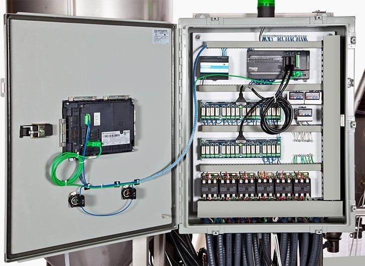 Basic electrical design of a PLC panel – Wiring diagrams (on photo: Modern industrial automation panel; credit: plctrg.com)
In some factories, the electricians also enter the ladder logic and do debugging. This article discusses the design issues in implementation that must be considered by the designer.
Electrical wiring diagrams of a PLC panel
In an industrial setting a PLC is not simply “plugged into a wall socket”. The electrical design for each machine must include at least the following components.
- Transformers – to step down AC supply voltages to lower levels
- Power contacts – to manually enable/disable power to the machine with e-stop buttons
- Terminals – to connect devices
- Fuses or circuit breakers – will cause power to fail if too much current is drawn
- Grounding – to provide a path for current to flow when there is an electrical fault
- Enclosure – to protect the equipment, and users from accidental contact
This power must be dropped down to a lower voltage level for the controls and DC power supplies. 110Vac is common in North America, and 220 V AC Is common in Europe and the Commonwealth countries. It is also common for a control cabinet to supply a higher voltage to other equipment, such as motors.
Motor controller example
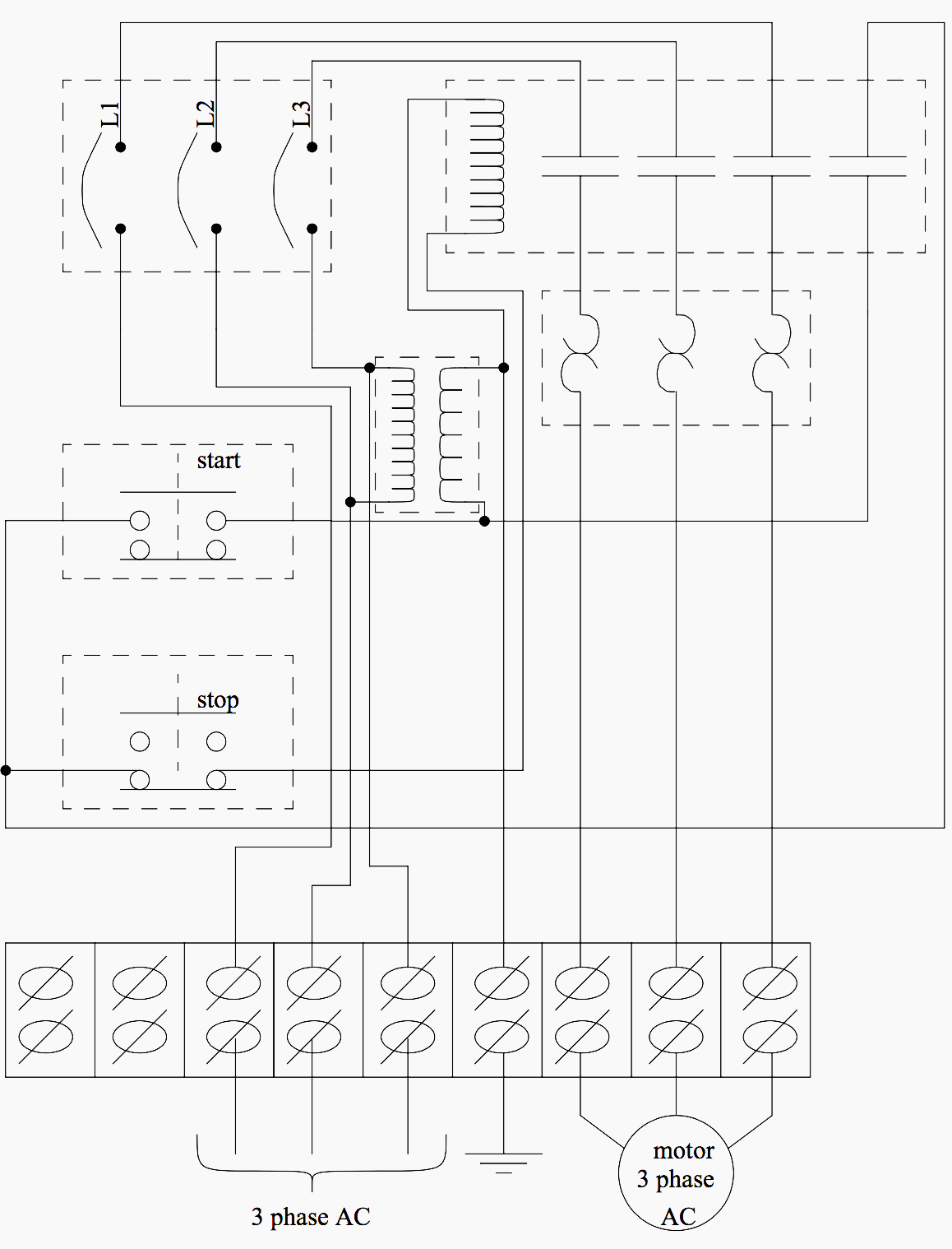
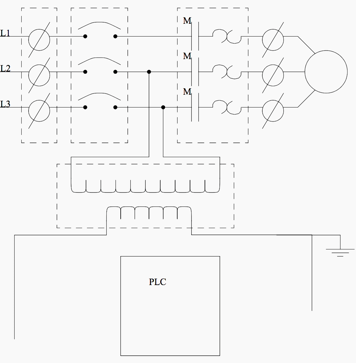
An example of a wiring diagram for a motor controller is shown in Figure 1. Note that symbols are discussed in detail later).
Dashed lines indicate a single purchased component. This system uses 3 phase AC power (L1, L2 and L3) connected to the terminals. The three phases are then connected to a power interrupter. Next, all three phases are supplied to a motor starter that contains three contacts, M, and three thermal overload relays (breakers).
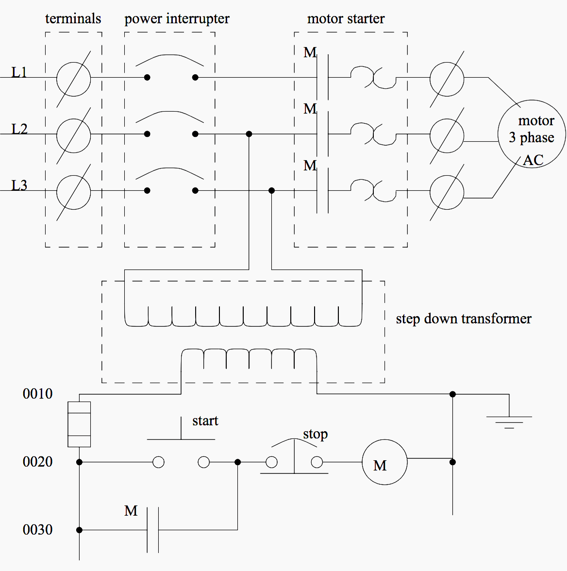
The contacts, M, will be controlled by the coil, M. The output of the motor starter goes to a three phase AC motor. Power is supplied by connecting a step down transformer to the control electronics by connecting to phases L2 and L3. The lower voltage is then used to supply power to the left and right rails of the ladder below. The neutral rail is also grounded.
The logic consists of two push buttons:
- Start push button is normally open, so that if something fails the motor cannot be started.
- Stop push button is normally closed, so that if a wire or connection fails the system halts safely.
The system controls the motor starter coil M, and uses a spare contact on the starter, M, to seal in the motor starter.
Aside: The voltage for the step down transformer is connected between phases L2 and L3. This will increase the effective voltage by 50% of the magnitude of the voltage on a single phase.
The diagram also shows numbering for the wires in the device. This is essential for industrial control systems that may contain hundreds or thousands of wires. These numbering schemes are often particular to each facility, but there are tools to help make wire labels that will appear in the final controls cabinet.
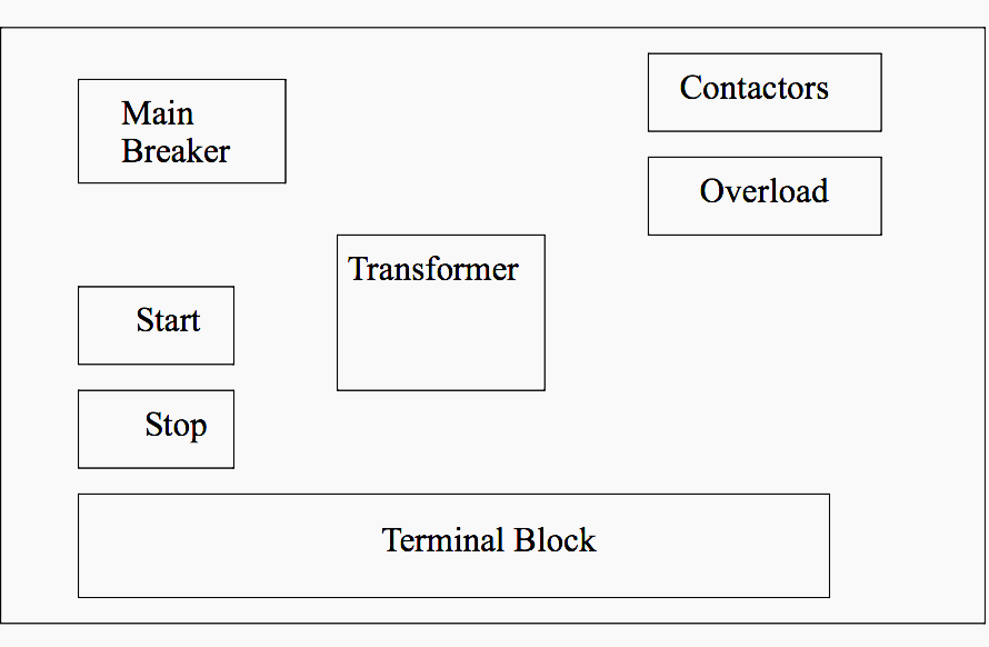
In the cabinet the AC power would enter at the terminal block, and be connected to the main breaker.
It would then be connected to the contactors and overload relays that constitute the motor starter. Two of the phases are also connected to the transformer to power the logic. The start and stop buttons are at the left of the box (note: normally these are mounted elsewhere, and a separate layout drawing would be needed).
The final layout in the cabinet might look like the one shown in Figure 1.
When being built the system will follow certain standards that may be company policy, or legal requirements. This often includes items such as;
- Hold downs – the will secure the wire so they don’t move
- Labels – wire labels help troubleshooting
- Strain reliefs – these will hold the wire so that it will not be pulled out of screw terminals
- Grounding – grounding wires may be needed on each metal piece for safety
A photograph of an industrial controls cabinet is shown in Figure 4:
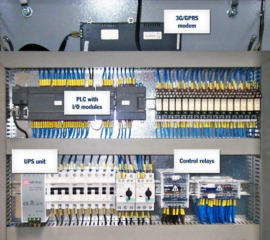
When including a PLC in the ladder diagram still remains. But, it does tend to become more complex. Figure 5 below shows a schematic diagram for a PLC based motor control system, similar to the previous motor control example.
This figure shows the E-stop wired to cutoff power to all of the devices in the circuit, including the PLC. All critical safety functions should be hardwired this way.
Electrical control panels including PLCs and HMIs
Reference // Automating manufacturing systems with PLCs by Hugh Jack
Related electrical guides & articles


Edvard Csanyi
Hi, I'm an electrical engineer, programmer and founder of EEP - Electrical Engineering Portal. I worked twelve years at Schneider Electric in the position of technical support for low- and medium-voltage projects and the design of busbar trunking systems.I'm highly specialized in the design of LV/MV switchgear and low-voltage, high-power busbar trunking (<6300A) in substations, commercial buildings and industry facilities. I'm also a professional in AutoCAD programming.
Profile: Edvard Csanyi

i want to know what is industrial and how to connect two way switch
I am a qualified construction electrician as code or article 28.Need to do and need help with panels and control circuit how can I learn easy way to wire or/and wire panels or learn contacts to use so that circuits can work according to.3
First learn or note the device and components required in the panel than learn its symbol,then read and learn the circuit drawing from the start to the end.For PLC you have to learn DI and DO,AI and AO and also its output type whether it relay based or not,then learn what things do you want to control like a lift you need a switch,DI,and relay output to the lift.
How to wire a main electrical cabinet
Design of Control panel PLC & Servo base for Application of Automatic Thermocol Product Manufaturing Machine
thanks for the materials above
will like to learn all new upload
Great
Good day,
are you able to make pump control repeater panels from the existing pumps to new repeater given a wiring diagram with specs.
if possible please contact me.
Thanks for sharing this blog. I stumbled here while I was looking to learn more about electrical panels because we are one of the leading Control Panel Manufacturers
Dear Sir,
your presentation is good. what you learn to me. immediately understood the your plc language.
Thank you Ajit.
I want drawings PLC and panel board and
can i request plc installation together the conection of thermocouple network to operate burner system and also motor connection using plc ..
Hi I have experience in PLC programming, installation and commissioning for any type of controls. I had done it for food production plants, Marine (trawlers) in past 20 years in Gulf countries and India. You can cater your controls as you wish with any PLC. This article is a worth one for beginners. Now I am working in operation side, automation is developed until the power distribution and generation fields. Should you require any technical helps dont hesitate to contact me for any facility and installations
Dear Sir
Can you able to explain, how to beginners make himself as more interesting to learn PLC Programming
Can you share any PDF File ?
Please can you share a PDF on electrical control and panel design. email: [email protected]
Hi Anil, can you send me your email address? I wanted to ask you few things related to control panels. Thanks
Sir,I am a beginner in the field of PLC , but very eager to become a perfect programmer in practical applications. Your kind advice / guidance is requested pl
Dear Sir,
we are interested indesigning in seawage water plant automation, so i need you guidence,can you.
Regards
H.B shinde
+919422221689
Can you help me regarding in my request ?
Hi, I am really interested in this type of work, I am a maintenance engineer and have basic skills with regards to electrical control panels etc. Could you recommend some books that will help me develop my skills and get a good understanding of wiring control panels and plc. Thanks
Hi sir i need your contact number, I need some help in PLC programming that to be done in existing starter panel for an Unmanned Barge.
Hello sir,
Compliments, ma i have the pdf material for this article. Thanks.
Sir, please send me the article of PLC control panel components wiring structure and how to design it.
Electric circuit for metal spinning machine controlled by plc
Nice information.
An electrical technician I want to be very good in p l c programming
What is the use of having a small transformer on the neutral at the star point of the generator to ground and then a resistor?
I want design and wiring PLC panel for aluminum die casting machine
what about control wiring diagram with PLC controler.
please send me a typical PLC & man controlled wiring diagram.
You used ‘M’ here.The diagram creates confusion I can’t able to understand.motor wiring diagram M letter use causes confusion.so clear my doubt.
A coil has a contact normally open and normally close so in the case the normally open of the coil contact is been used as a retainer to retain the contact when u remove ur hand from the push button. And is because u re making use of a push button if is to be a latch switch u dnt need that
I like to know, what size of the copper cable used on the megger machine to test the slope, touch potential on the earth grid of the distribution substation.
This article on basic design on PLC Panel was good, informative and can be a good learning.