Continued from 1st part: Electrical Design Project of a Three Bed Room House (Part 1)
Building regulations
Smoke detectors
All new domestic dwellings, including conversions, must either have:
- A fire detection and fire alarm system in accordance with the relevant recommendations of British Standard BS 5839-6 system; or
- Mains operated smoke alarms, with at least one on each floor and interconnected.
Load assessment
The Regulations require that the characteristics of the supply, including an assessment of the maximum demand, should be determined by calculation, measurement, enquiry or inspection.
The other characteristics may be determined by enquiry to the electricity company (Distributor). Some of the Distributors publish guidance on the electricity supply characteristics and requirements for systems.
As a rule of thumb follow these steps to calculate the total demanded load:
- Step I: indicate buildings (rooms) in project
- Step II: find total connected load of a building in kVA for example
- Step III: apply appropriately the demand factor, load factor and diversity factor.
- Step IV: consider the future expansion of the service (25%).
A typical domestic supply
Except in unusual circumstances, supply characteristics are:
- Prospective short-circuit current at the origin:
Never more than 16 kA and more likely to be less than 2 kA; - External earth fault loop impedance Ze:
Not exceeding 0.35 Ω (for TN-C-S) and more likely to be less than 0.2 Ω; - Main fuse:
This will be to the usual Distributor standard, BS 88-3 (previously BS 1361, Part 2) 100 A. Provided that these figures apply, there should be no problems in applying a standardized electrical design.
Project specification
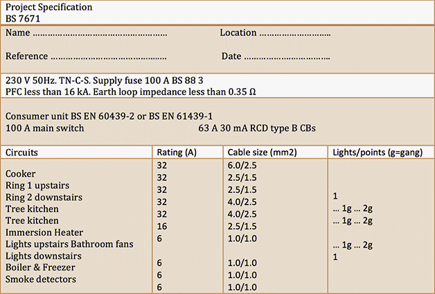
It is necessary to produce a Project Specification, as in Table 2 below. This will be used initially for pricing and technical purposes. It will eventually be updated to form the basis of a user manual.
Table 2 – Project Specification (acc. to BS 7671)

Wiring systems and cable sizes
Circuits and circuit design are two important discussions that every electrical engineer should know it. Traditionally, domestic installations have been wired using the ‘three plate rose’ lighting system and ring circuits for the socket-outlets.
As a rule of thumb follow these steps to design your cable circuits:
Step I:
Determine the supply characteristic including earthing arrangement. I prefer TN-C-S. Adopted value for Ze is 0.35 Ω. Next, find the design current Id from the total demanded load.
Step II:
Select cable and protective device (PD) size. Always make sure that Ipd ≥ Id. Next, select a cable size from Appendix 4 of BS 7671 which can carry the load It. Always make sure that:
![]()
Where:
- Cg = Rating factor for grouping. Table 4 C1 of BS 7671
- Ca = Rating factor for ambient temperature. Table 4 B1 of BS 7671
- Ci = Rating factor for conductors surrounded by thermal insulation. Table 52.2 of BS 7671
- Cf = Rating factor for semi-enclosed fuse. BS 3036
Step III:
Check for voltage drop. Use this equation to make sure the minimum cross section is OK.

Where:
- Vd = Voltage drop in volts.
- L = Cable length in meters
- mV/A/m = The value from appropriate table. Appendix 4 of BS 7671
This voltage drop should be equal to or lower than the appropriate voltage drop percentages given in Table 4Ab of Appendix 4 of BS 7671. (Vd/230)·100% for a nominal voltage of 230V.
Step IV:
Check for electrical shock. The earth fault loop impedance Zs at the furthest point of the circuit must be determined by using the following formula:
![]()
Where:
- R1 + R2 is the resistance per meter of the line and protective conductor.
- Cr is the rating factor for operating temperature
- Ze is the value of external earth fault loop impedance.
The value of Zs must be less than the value given in Tables 41.2, 41.3 or 41.4 of BS 7671.
Step V:
Check for prospective fault current. Live conductor are protected against short circuit currents if their value of k2S2 must be greater than the value of let-through energy I2t for the protective device.
Where:
- S is the cross sectional area of conductors
- k is the value taken from Table 43.1 of BS 7671.
First find the short circuit current by:
![]()
Where:
- ZLN is line to neutral impedance at the origin of the installation
- R1 + Rn is the resistance per meter of the line conductor and neutral conductor
- t is the operating time of the protective device determined from time/current characteristic given in Appendix 3 of BS 7671.
Copyright Notice
This technical article is protected by U.S. and international copyright laws. Reproduction and distribution of PDF version of this technical article to websites such as Linkedin, Scribd, Facebook and others without written permission of the sponsor is illegal and strictly prohibited.© EEP-Electrical Engineering Portal.
Related electrical guides & articles
Premium Membership
Sufi Shah Hamid Jalali
B.Sc. in Electrical Engineering. Designer of websites. Currently working as Electrical Engineer at Aga Khan Foundation, Afghanistan. Likes to write and share knowledge of Electrical Engineering. Knows Primavera P6, Graphics, Professional AutoCAD and Project Management.Profile: Sufi Shah Hamid Jalali


great
Like super simple
I need electrical description on domestic building