
Estimated Study Time: 29 minutes
Electrical design considerations
Electrical systems within a nuclear power plant (NPP) deserve significant design considerations. The availability of on-site as well as off-site power plays a crucial role in nuclear power plant safety and are one of the most important considerations in constructing a new NPP nuclear power plant.
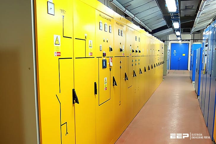 Internal electrical systems within nuclear power plant stations (on photo: DC switchboards in the Dukovany Nuclear Power Plant. These switchboards distribute electricity between the rectifier, the battery and DC consumers, protects outlets against overload, cycling and capacity testing of the battery. credit: ic-energo.com)
The electrical systems are designed not only for normal plant operation, but also for conditions other than normal operation, so that plant safety can be maintained by ensuring continuity of electrical power supplies regardless of transient disturbances or faults during operation and post-shutdown.
This technical article explains internal electrical systems within CANDU (CANada Deuterium Uranium) nuclear power plants.
- Sources of Electrical Power
- Class Definition of Power Sources
- Channelization
- Electrical Power Sources under Different Classes
- Load Transfer among Different Buses
- Standby Generators (SGs)
- Emergency Power Systems (EPS)
- Grounding and Lightning Protection
- Control of Electrical Loads
1. Sources of Electrical Power
Almost all systems within an nuclear power plant rely on electrical power to operate. A defence-in-depth strategy for electrical power supplies is to rely on diverse, multiple, and independent sources.
These sources for a NPP CANDU unit are:
- Power generated from the unit itself
- Power generated from other units within the same station
- Off-site power obtained from the grid
- The emergency power supply
- The standby power supply and
- Batteries
The power sources in a nuclear power plant consist of both AC (alternating current) and DC (direct current) power.
Defence-in-depth
Defence-in-depth strategy as applicable to the electrical systems can be stated as follows:
- 1st line – Normal operation (grid + main generator)
- 2nd line – Mitigation (standby generators + batteries)
- 3rd line – Station blackout (batteries + designated alternative source(s))
- 4th line – Severe accident management (additional, diverse, alternative sources).
These sources are arranged in such a way that they supply power to station systems during normal operation, as well as during emergency conditions to maintain NPP safety.
The equipment in the station is also graded according to its importance to safety. In an event that electrical generation is lost, limited alternative power sources will be used first and foremost to keep the essential safety-related systems operating.
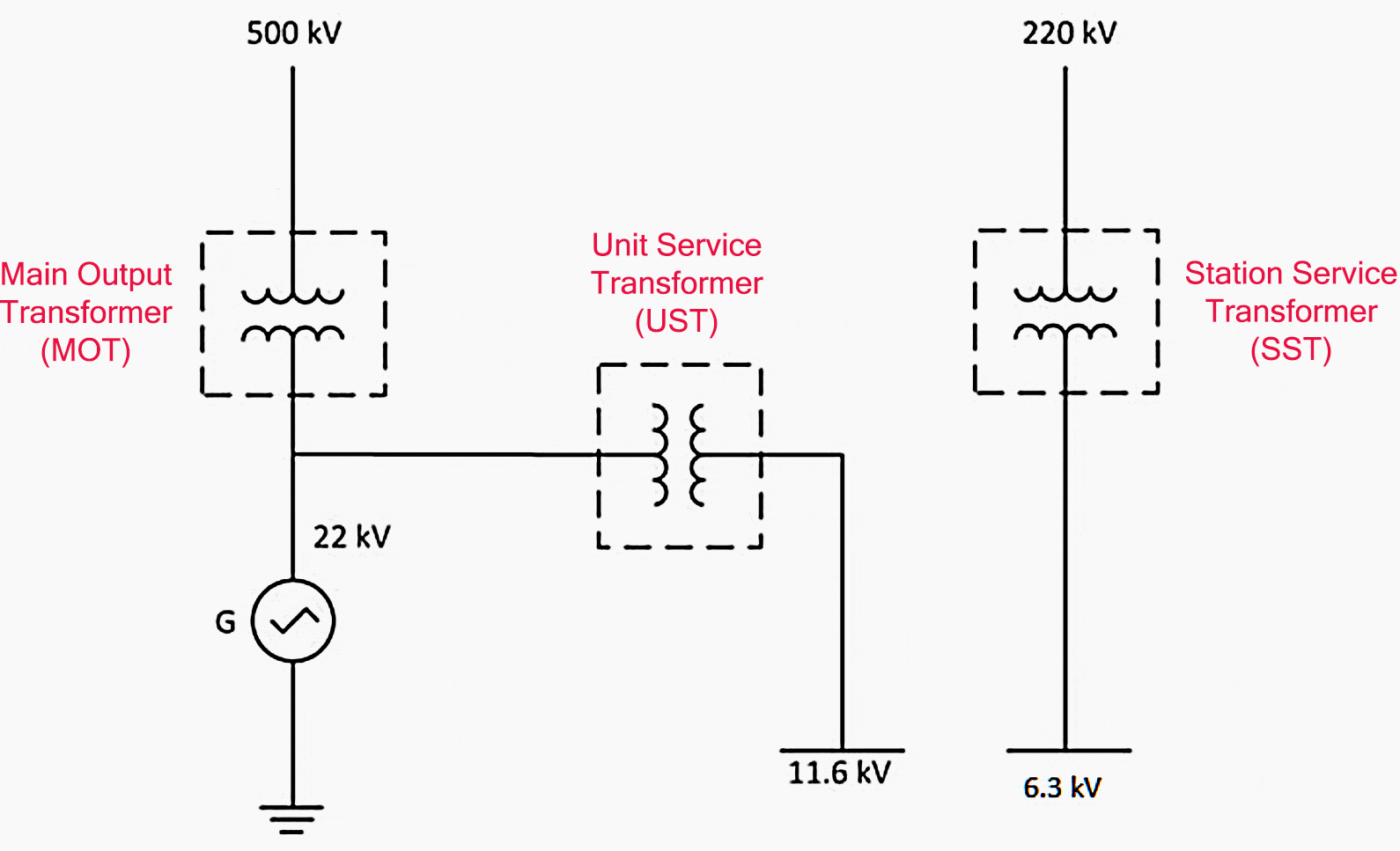
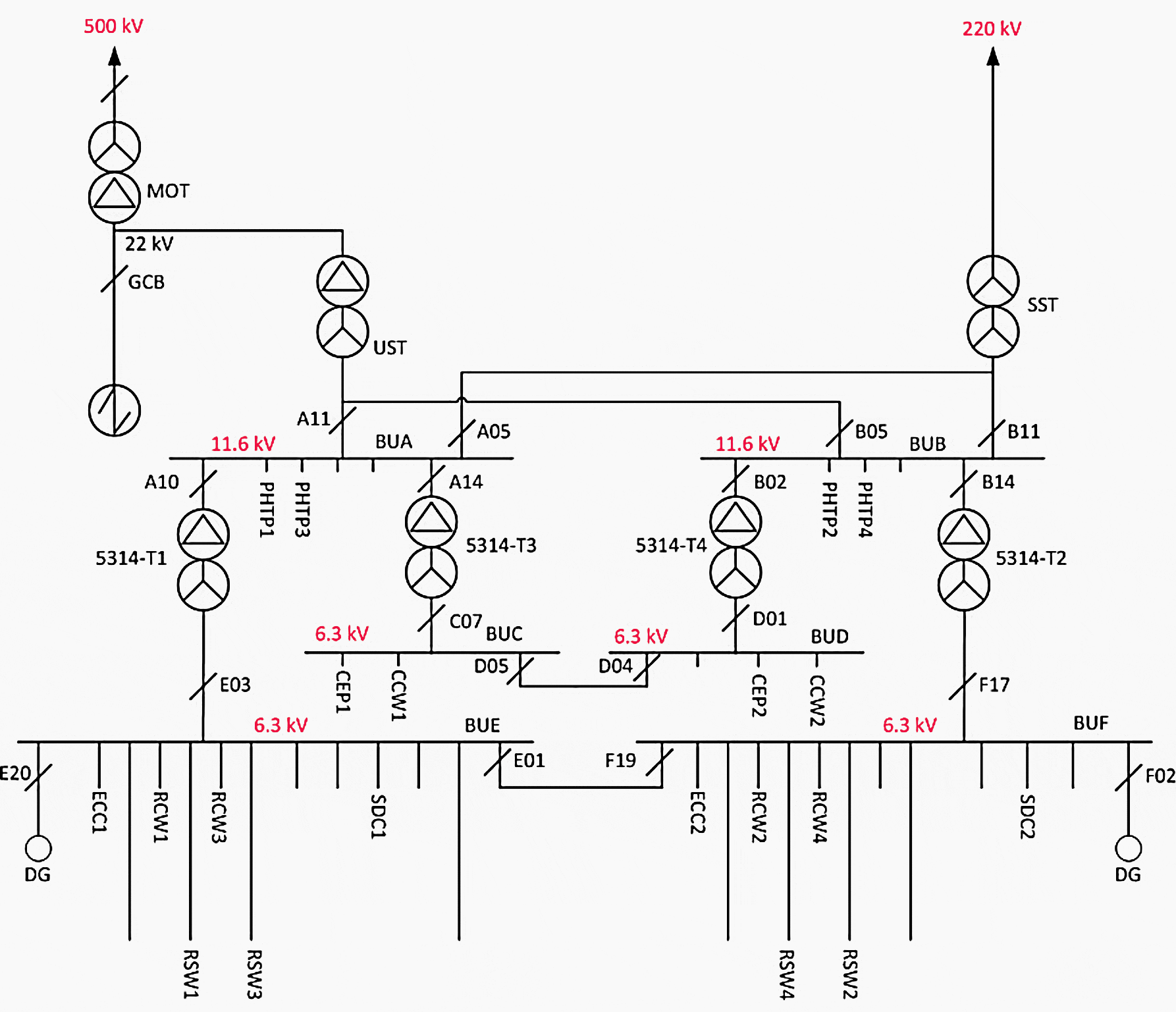
A CANDU plant contains several buses at different voltage levels. The selected voltage levels might be different in different plants to meet certain country-specific requirements.
One exampleplant is shown in Figure 1, where the output voltage level of the generator is at 22 kV, and the voltages at the unit service transformer (UST) and the station service transformer (SST) are at 11.6 kV and 4.16 kV as secondary voltages.
However, in other designs, these voltages could be 13.8 kV and 4.16 kV. Also shown in Figure 1 are two connections to off-site power at the NPP site, one at 500 kV and the other at 220 kV.
2. Class Definition of Power Sources
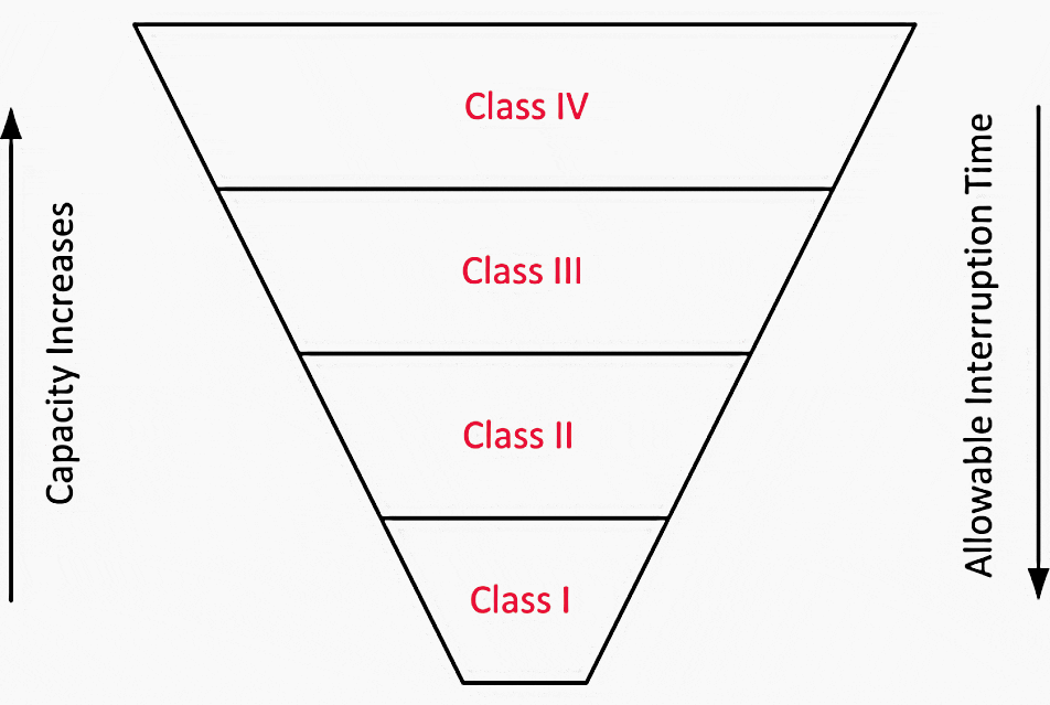
Electrical power sources in a CANDU plant can be divided into four levels, according to the allowed duration of voltage interruption that can be tolerated by the loads they supply.
The most critical and safety-related control and protection systems are powered from Class I and II sources.
Different classes of power supplies provide power to different systems, depending on the amount of power the systems require and their relative importance to safety. Typically, the cost per kW will decrease as the power supplies move from Class I through to Class IV. The power capacities also increase from Class I to Class IV.
The allowable interruption times and capacities of the various power sources are summarized in Figure 2:
To determine which class of power should be used to supply a specific system, the safety functionalities of the system must be examined, as well as the economic impact if that supply were unavailable.
General criteria for matching the class of power supply to the load that it supports are summarized in Table 1. They are expressed in terms of the longest power interruptions that will not affect the safety of either the NPP or its personnel.
Table 1 – Classification of power sources
| Class of power | System load characteristics |
| Class I | Power can never be interrupted under postulated conditions |
| Class II | Power can be interrupted up to 4 milliseconds |
| Class III | Power can be interrupted up to 5 minutes |
| Class IV | Power can be interrupted indefinitely |
Different stations may have slight variations in electrical power system configurations.
An illustrative diagram showing interconnections in the electrical power system for the different classes of power sources in a CANDU station is presented in Figure 3.
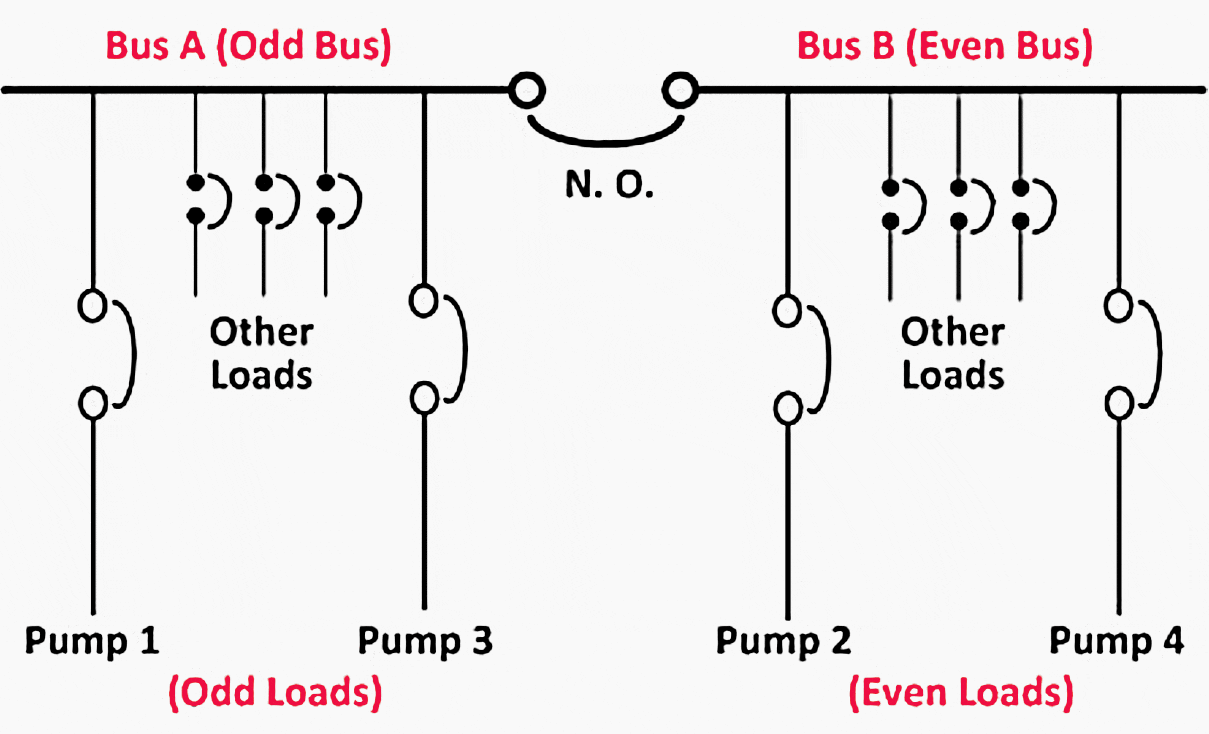
To increase reliability further, Class II, III, and IV power are distributed through two separate power divisions. If a failure occurs on one division, the equipment connected to the other bus will still be available.
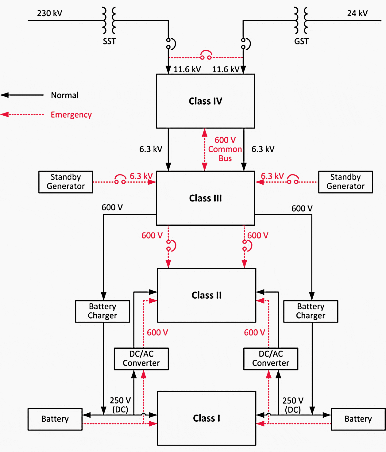
In CANDU plants, these two divisions are typically denoted as “Bus A” and “Bus B” or as “Odd Bus” and “Even Bus”. During design, loads are distributed evenly between these two divisions.
An example of such a split-bus connection is shown in Figure 4.
To accomplish the connection, both breakers must be manually commanded to close.
3. Channelization
Important functions use three instrument channels to provide immunity against single instrument faults. A control channel consists of interconnected hardware and software components that process one of the duplicated or triplicated signals associated with a single parameter.
For safety and high-reliability applications, I&C system design uses three instrumentation channels with a two-out-of-three voting strategy (i.e., two of the three channels must be outside the acceptable limits to trip or actuate the system).
4. Electrical Power Sources under Different Classes
4.1 Class I
Class I power is used to supply loads that cannot be interrupted. It is a DC power source with three independent distribution channels, each backed with battery banks to provide uninterrupted power to critical loads.
To maintain adequate charge on the batteries, each bus in Class I is connected to power rectifiers, which convert AC power from Class III power sources to DC to charge the batteries, as shown in Figure 3.
Note that the batteries are capable of supplying the load on the DC buses for only about 60 minutes, depending on the particular plant design. This is a very critical time window because all Class I and II power would be lost if Class III power could not be restored within the interval provided by the batteries.
The loads supported by the Class I power source are very sensitive and are critical to NPP safety and operation. A partial list of system equipment powered from Class I is provided in Table 2.
Table 2 – Equipment supported by Class I power supplies
| Equipment supported by Class I power supplies | |
| 1 | Class II inverters |
| 2 | DC seal oil pumps for generator |
| 3 | DC lube oil pump for turbine generator bearings |
| 4 | Turbine trip circuits |
| 5 | Turbine turning gear |
| 6 | DC stator cooling pumps |
| 7 | Control and protection systems for station electrical distribution systems |
| 8 | Logic, control, command circuits, and operator interfaces for process and safety systems (48 VDC) |
The capacity of the Class I power source is based on the connected load. CANDU plants use several different voltage levels for this DC power supply, including 48V, 220V/250V, and 400V, all to meet the needs of the NPP’s various systems.
Note that loss of Class I power is one of the conditions that trigger the shutdown systems.
To prevent service interruption caused by a “single line-to-ground” fault, the 48V DC and 250V DC systems are ungrounded. Ground fault detectors, which produce an alarm whenever a ground fault occurs, are provided for each bus.
4.2 Class II
Class II power sources are critical to reactor operation. If Class II power is lost, the reactor will be shut down immediately. Under normal operation, Class II power is obtained from Class I sources through power inverters to convert DC power to AC power, as can be seen in Figure 3.
The Class II power source supports those devices and systems that can tolerate power interruptions on the order of milliseconds. Some typical systems supported by Class II power source are listed in Table 3.
Table 3 – Equipment supported by Class II power supplies
| Equipment supported by Class II power supplies | |
| 1 | Digital control computers |
| 2 | Reactor regulation instrumentation |
| 3 | Electrically operated process valves (600 V power distribution) |
| 4 | Auxiliary oil pumps on the turbine and generator (600 V power distribution) |
| 5 | Emergency lighting (600 V power distribution) |
Three independent channels of single-phase inverters ensure complete supply independence to the triplicated instrumentation and I&C. Class II power sources are relatively low-capacity, have two voltage levels: 120V and 600V, and are available only in AC form.
4.3 Class III
Class III power supports large process loads that are unsuitable for Class II power supplies. They are used mainly to maintain fuel cooling when the reactor is in a shutdown state and Class IV power is unavailable.
It is important to note that the duration of the loss of Class III power consists of only the time required to start up a standby generator and re-load the Class III power system, which is normally about five minutes.
This improves the reliability of Class III power, making it available even in the presence of partial loss of Class IV power sources.
If the Class IV power source for a unit fails completely, it is still possible to obtain Class IV power from other units in a multiple-unit station. Once the standby generators are started, they will provide power to systems supplied by the Class III power source, ensuring that these critical systems remain functional.
Some typical systems supported by Class III power sources are listed in Table 4.
Table 4 – Equipment supported by Class III power supplies
| Equipment supported by Class III power supplies | |
| 1 | Auxiliary boiler feed pumps |
| 2 | Auxiliary condensation extraction pumps |
| 3 | Shutdown system cooling pumps |
| 4 | Turbine turning gear |
| 5 | Heat transport feed pumps |
| 6 | Moderator circulating pumps |
| 7 | Class I power rectifiers |
| 8 | Fire water pumps |
| 9 | Emergency core coolant injection pumps |
| 10 | Instrument air compressors |
| 11 | End shield cooling pumps |
| 12 | Service water pumps |
The voltage level of Class III power is 4.16 kV, and its capacity can range from 6 to 8 MWe.
4.4 Class IV
Of the four classes of power sources in a NPP, Class IV supplies loads that can tolerate infinite interruption. This power can come from two sources. During normal operation, Class IV power is obtained from the main generator through the unit service transformer (UST).
Using power produced internally by the plant’s own generator minimizes the potential impact of disturbances from the grid. Class IV power can also be obtained from the grid through the station service transformer (SST) when the UST becomes unavailable.
The loads normally supplied by Class IV power are systems which can tolerate long-term power outages without affecting the safety of equipment, personnel, or the public. These loads are not essential to satisfy fuel cooling requirements following a reactor or turbine trip, but are essential for operation of heat sinks above the shutdown level of reactor power.
Some typical systems supported by Class IV power sources are listed in Table 5.
Table 5 – Equipment supported by Class IV power supplies
| Equipment supported by Class IV power supplies | |
| 1 | Main boiler feed pumps |
| 2 | Main heat transport circulating pumps |
| 3 | Condenser cooling water pumps |
| 4 | Generator excitation |
| 5 | Heating and ventilation equipment |
| 6 | Normal lighting systems |
5. Load Transfer among Different Buses
As shown in Tables 2 to 5, nuclear power plant system loads are distributed among the various buses based on their size and importance to system safety.
Figure 5 provides an illustrative load diagram for the Class IV and Class III power buses.
These specific transfer schemes are used at the upper voltage level of Class IV to prevent reactor trip and maintain generation production.
The parallel transfer mode consists of two steps:
- Parallel the new power source to the existing one, and
- Remove the existing one to complete the transfer. A fast transfer switches the load quickly (within two power cycles) so that little interruption is observed.
The slow transfer operates after the voltage has decayed to approximately 40% to limit the maximum voltage that could be applied to a connected load upon re-energization and can be used only if the supply transformers can tolerate the inrush currents and if the voltage drop does not prevent loads from being re-accelerated to nominal speeds.
Class IV transfers are manually initiated for normal transfers after start-up or before shutdown and are automatically initiated for reactor trips, turbine-generator trips, or loss of the transmission system.
Automatic transfer systems are also incorporated into Class II. They monitor the operation of the power inverters and under certain conditions, transfer Class II distribution buses to alternative supplies directly from Class III. These transfers operate within each channel or division of Class II.
6. Standby Generators (SGs)
To maintain power to safety, safety support, and heat-sink systems following loss of Class IV power sources, CANDU stations contain additional on-site power sources.
One type is known as standby generators. These generators are not required to be seismically qualified. This power source is based on two or more generators driven by diesel engines or combustion-turbines (in the case of Ontario Power Generation).
As shown in Figure 3 and Figure 5, a generator supplies Class III AC power to each Odd and Even bus at a 6.3 kV level. These generators are supplied with enough fuel to keep the diesel engines running continuously for an extended period of time (up to one week depending on a continued supply of fuel).
The SGs could form a seismically qualified distribution system, but the design has evolved to create a separate seismically qualified distribution system.
The seismically qualified systems are connected to Class III because that is their preferred source of power and are isolated from Class III only when the seismically qualified power sources can provide the required power.
The standby generators will also start whenever a loss-of-coolant accident (LOCA) signal is issued, but will not connect to the buses until a loss of Class IV power occurs. Standby generators should be up and running within 30 seconds after receiving a LOCA signal, picking up all designated loads within a further three minutes.
One standby generator has sufficient capacity to supply the required loads.
Because of the critical roles played by standby generators, regular maintenance is critically important. This typically consists of starting each diesel generator periodically from the local control panel, paralleling it with the respective division of the Class IV supply, and letting the generators run for a specified minimum period of time.
7. Emergency Power Systems (EPS)
The second set of alternative power sources in CANDU plants is known as emergency power systems. Unlike standby generator systems, these power sources must be seismically qualified, and they function completely independently of other power sources.
Similarly to standby generators, the emergency power systems start automatically upon the loss of Class IV power and will also start on a LOCA signal. Under such circumstances, back-up generators provide power to the NPP’s critical systems to enable reactor shutdown, monitoring, and decay heat removal.
It is expected that the system should be up and running with its intended loads within three minutes.
8. Grounding and Lightning Protection
The grounding system is required to prevent physical injuries and equipment damage in case of a fault and to minimize electromagnetic effects from ground fault currents as well as to prevent interference and to protect equipment from lightning strikes.
Lightning protection is required so that equipment related to the safety of the nuclear power plant continues to operate and important monitoring devices continue to function when lightning hits facilities or power lines.
9. Control of Electrical Loads
Generally, in a typical CANDU power generating station, the electrical loads are remotely controlled using the control logic (relay logic) and interposing circuits, both powered from 48 V DC Class I.
The output from the control logic is hard-wired to the switchgear and motor control centre (MCC) control circuits or to the terminals of a solenoid valve when the valve is controlled directly.
In the AUTO mode, the load will augment the already running load(s) when the process demand exceeds the capacity of the running load(s). In the STANDBY mode, the load will replace the normally running load when the latter fails to operate.
9.1 Loads powered from switchgear
Power to the various loads is switched ON and OFF by an individual circuit breaker at the selected voltage level. The circuit breaker protective relays may be mounted within the breaker cell, and the relays interposing between the breaker control circuit and the load’s control logic are located in separate cubicles or cells, called the relay and terminal section, adjacent to each group of circuit breakers.
A typical switchgear control circuit operates from the 250 V DC power source provided by the Class I batteries.
The circuit is used to:
- Provide power to the operation of stored-energy devices which operate on the close and trip mechanisms of the circuit breaker.
- Close and trip the circuit breaker in response to commands from the:
- Unit operator
- Process control system
- Power circuit protective relays
Operation of the close and trip circuits requires momentary signals. The circuit breaker controls require manual local reset following a trip due to the operation of power circuit protective relays.
9.2 Loads powered from the MCC
Power to these loads will be switched ON and OFF by contactors in individual combination starters. The relays interposing between the contactor control circuit and the load’s control logic are located in the relay and terminal section adjacent to each group of combination starters.
The circuit breaker in the combination starter is manually operated and, except for maintenance, remains in the closed position.
A typical MCC control circuit operates from the 120 V AC power source provided by the starter’s step-down transformer.
To remain energized, the contactor requires a signal to be maintained. The circuit breaker requires a manual local reset following a trip due to the operation of power circuit protective functions built into the breaker.
9.3 Class IV and Class III loads
Typical types of interfacing circuits are: MCC and switchgear, MCC only and other
9.4 Class II and Class I loads
Loads energized from the Class II and Class I (UPS) MCCs or panels perform either special safety-related or personnel/equipment protection-related functions.
9.5 EPS loads
Loads energized from the EPS are controlled in the same way as when they were energized from Class III, II, and I or will be limited to manual OFF/ON controls.
Source: The University Network of Excellence in Nuclear Engineering (UNENE); Dr. Jin Jiang at Department of Electrical & Computer Engineering Western University and Mr. Alek Josefowicz, P.Eng., CANDU Energy
Related electrical guides & articles


Edvard Csanyi
Hi, I'm an electrical engineer, programmer and founder of EEP - Electrical Engineering Portal. I worked twelve years at Schneider Electric in the position of technical support for low- and medium-voltage projects and the design of busbar trunking systems.I'm highly specialized in the design of LV/MV switchgear and low-voltage, high-power busbar trunking (<6300A) in substations, commercial buildings and industry facilities. I'm also a professional in AutoCAD programming.
Profile: Edvard Csanyi

Dear Edvard Csanyi, I find articles in EEP very useful and I believe my linked-in connections would benefit by sharing these articles. May I know if I can share this and any other articles from EEP portal in Linked-in? If yes, How do I go about sharing?