
Estimated Study Time: 26 minutes
Never underestimate EMC issues
The search for an overall optimization of the installation with regard to electromagnetic compatibility (EMC) and its ability to function without suffering or emitting excessive interference, comes via a set of good practices, which are often simple and based on common sense.
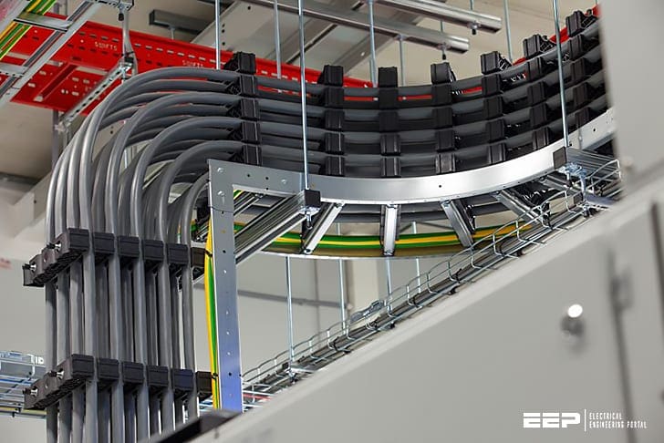 Good practice rules for electromagnetic compatibility (EMC) of LV conductors (photo credit: Joop Gijsbers)
They apply to power and to communication conductors, and to both where they have to cohabit.
Essential components in the installation, metal cable tray and prefabricated trunking contribute to the control of EMC in several ways. First, they constitute a common, continuous and distributed potential reference, by integrating into the installation’s earthing system.
They also provide an interference reduction effect by reducing couplings due to proximity or the interposing of conductive elements,
Metal cable tray and prefabricated trunking enable the geometrical separation of circuits and functions and also compliance with minimum cohabitation distances between high and low currents and between polluting and sensitive circuits. It should be noted that insulating ducts and tray also have this advantage,
Cable tray, trunking and more generally products intended for the transport and distribution of energy and communications in installations are considered as passive elements for EMC purposes.
This is undoubtedly a slightly simplistic view, given that conductors operate as aerials which radiate and receive and that they are subject to multiple couplings. but at the same time, EMC phenomena are highly complex to analyse within an overall installation The routes taken by conductors and what they are exposed to are diverse and variable.
1. Electrical continuity of cable trays
Where it is correctly inter-connected and connected to the installation’s general equipotential link, metal cable tray contributes to the constitution of a common distributed potential reference, with a low impedance, which improves the quality of the installation’s general earthing system.
Standard IEC 61537 requires electrical continuity in cable tray which is stated as being conductive.
Maximum electrical resistance values are 5 mΩ per metre and 50 mΩ per joining contact. Even though the first value is compatible with the right conductivity for HF interference, the second is much too high. A maximum target value of 1 mΩ must be sought and a value of 5 mΩ should not be exceeded under any circumstances.
1.1 Physical continuity of cable tray
Wire joins are to be avoided due to their high impedance at high frequencies. it is recommended that continuity is produced by using appropriate items that produce much more effective wide and flat contacts.
1.2 Star earthing system and common mesh system
Standard EN 50174-2 gives information on three levels for producing equipotential and earthing systems for communication installations. The search for maximum meshing reduces the impedance of the various circuits and equipment. This star earthing system is usually used in small installations. It only relates to distributed protection conductors, in a star, from the installation’s origin.
Equipment items do not communicate with each other or, if they do, they only do so locally. We then talk about a star multiple mesh system (see below).
In a common meshing system, it is the whole installation where conductive items, earths and protective conductors are meshed.
1.2.1 Star earthing system structure
As a general rule, when equipment items, but this is also true for cable tray, are remote from each other and are inter-connected by protective conductors, the earth network created has a low equipotential associated with a high common impedance between the various items.
The nature itself of the protective conductors and their cross-section has only limited influence.
By virtue of the star structure of the installation, they are too long, which results in too high a high-frequency impedance for the equipotential to be correct.
1.2.2 Structure of a common mesh earth system
In a common mesh earth system structure, metal cable trays are inter-connected to all available elements of the building’s structure (frames, hangers, etc.). A search for the electrical continuity of routings must also be done by adding, if necessary, a few linking items (hangers, crossovers, cable tray sections) to provide better inter-connection.
1.2.3 Star earth system structure with multiple meshes (variant of the star system)
Producing a full common meshing can be difficult (extent or complexity of the site, absence of conductive items) and it is sometimes preferable to deal with equipotential locally (unit mesh) for networks supplying certain equipment.
In the example in the diagram below, the two distinct runs of power and communication systems supplying a single piece of equipment are made equipotential by a connection to accessible local earths and to the equipment itself.
Edvard Csanyi
Hi, I'm an electrical engineer, programmer and founder of EEP - Electrical Engineering Portal. I worked twelve years at Schneider Electric in the position of technical support for low- and medium-voltage projects and the design of busbar trunking systems.I'm highly specialized in the design of LV/MV switchgear and low-voltage, high-power busbar trunking (<6300A) in substations, commercial buildings and industry facilities. I'm also a professional in AutoCAD programming.
Profile: Edvard Csanyi
