
Never underestimate EMC issues
The search for an overall optimization of the installation with regard to electromagnetic compatibility (EMC) and its ability to function without suffering or emitting excessive interference, comes via a set of good practices, which are often simple and based on common sense.
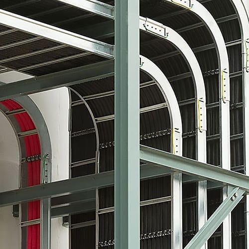
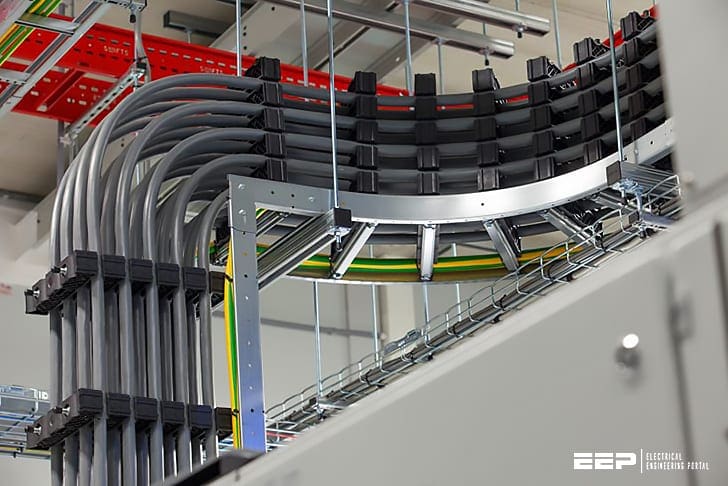 Good practice rules for electromagnetic compatibility (EMC) of LV conductors (photo credit: Joop Gijsbers)
They apply to power and to communication conductors, and to both where they have to cohabit.
Essential components in the installation, metal cable tray and prefabricated trunking contribute to the control of EMC in several ways. First, they constitute a common, continuous and distributed potential reference, by integrating into the installation’s earthing system.
They also provide an interference reduction effect by reducing couplings due to proximity or the interposing of conductive elements,
Metal cable tray and prefabricated trunking enable the geometrical separation of circuits and functions and also compliance with minimum cohabitation distances between high and low currents and between polluting and sensitive circuits. It should be noted that insulating ducts and tray also have this advantage,
Cable tray, trunking and more generally products intended for the transport and distribution of energy and communications in installations are considered as passive elements for EMC purposes.
This is undoubtedly a slightly simplistic view, given that conductors operate as aerials which radiate and receive and that they are subject to multiple couplings. but at the same time, EMC phenomena are highly complex to analyse within an overall installation The routes taken by conductors and what they are exposed to are diverse and variable.
1. Electrical continuity of cable trays
Where it is correctly inter-connected and connected to the installation’s general equipotential link, metal cable tray contributes to the constitution of a common distributed potential reference, with a low impedance, which improves the quality of the installation’s general earthing system.
Standard IEC 61537 requires electrical continuity in cable tray which is stated as being conductive.
Maximum electrical resistance values are 5 mΩ per metre and 50 mΩ per joining contact. Even though the first value is compatible with the right conductivity for HF interference, the second is much too high. A maximum target value of 1 mΩ must be sought and a value of 5 mΩ should not be exceeded under any circumstances.
1.1 Physical continuity of cable tray
Wire joins are to be avoided due to their high impedance at high frequencies. it is recommended that continuity is produced by using appropriate items that produce much more effective wide and flat contacts.
1.2 Star earthing system and common mesh system
Standard EN 50174-2 gives information on three levels for producing equipotential and earthing systems for communication installations. The search for maximum meshing reduces the impedance of the various circuits and equipment. This star earthing system is usually used in small installations. It only relates to distributed protection conductors, in a star, from the installation’s origin.
Equipment items do not communicate with each other or, if they do, they only do so locally. We then talk about a star multiple mesh system (see below).
In a common meshing system, it is the whole installation where conductive items, earths and protective conductors are meshed.
1.2.1 Star earthing system structure
As a general rule, when equipment items, but this is also true for cable tray, are remote from each other and are inter-connected by protective conductors, the earth network created has a low equipotential associated with a high common impedance between the various items.
The nature itself of the protective conductors and their cross-section has only limited influence.
By virtue of the star structure of the installation, they are too long, which results in too high a high-frequency impedance for the equipotential to be correct.
1.2.2 Structure of a common mesh earth system
In a common mesh earth system structure, metal cable trays are inter-connected to all available elements of the building’s structure (frames, hangers, etc.). A search for the electrical continuity of routings must also be done by adding, if necessary, a few linking items (hangers, crossovers, cable tray sections) to provide better inter-connection.
1.2.3 Star earth system structure with multiple meshes (variant of the star system)
Producing a full common meshing can be difficult (extent or complexity of the site, absence of conductive items) and it is sometimes preferable to deal with equipotential locally (unit mesh) for networks supplying certain equipment.
In the example in the diagram below, the two distinct runs of power and communication systems supplying a single piece of equipment are made equipotential by a connection to accessible local earths and to the equipment itself.
Notes:
Connections between masses are preferably made by bolting on directly (paint removed, metal/metal and restoration of the protection) or by connection systems approved by manufacturers (joining components, couplers, penetrating devices, etc.).
Short, wide conductors (braids, straps) may be used for shorter lengths (typically 0.5-1 m) or for complex geometrical layouts. round wire conductors should not be permitted beyond a few dozen centimeters.
Attention is nonetheless drawn to the necessary permanence of these items, to their actual role and possible incompatibility for integration into the overall earth network.
Some situations require a special analysis: presence of stray currents, return supply current, presence of lightning currents or particular interference, high immunity for hospital equipment, etc. Prior expertise is then necessary to assess the impact of the measures taken.
2. Reduction Effects
EMc good practice rules very often recommend positioning conductors as close as possible to masses or even pressing them against them, without however detailing the electromagnetic forces brought into play. We talk about a coupling reduction effect. In practice, it is especially communication conductors that can benefit from this effect.
This reduction effect has two aspects:
Aspect #1 – An inductive aspect modifying the conductors’ own impedance by reducing the self-induction component which increases with the frequency (see next page),
Aspect #2 – A capacitive aspect reducing crosstalk with the other conductors by modifying the capacitive coupling. The metal element introduces a third armature in the capacitors which conductors form between each other.
Even more than for the inductive model, it is very difficult to quantify the capacitance value which these conductive elements represent which are complex impedances (both capacitor armatures and inductances).
2.1 Rule for grouping conductors
Too close cohabitation of conductors leads to couplings and the transmission of interference. conversely, their being too far apart leads to poor equipotential and the creation of high surface loops.
As a compromise, it is preferable to route all conductors supplying a single system or devices communicating with each other relatively close together. This is particularly important for the protective conductor which participates in the capacitive coupling reduction effect.
In particular, it must not be separated from the active conductors by ferromagnetic elements.
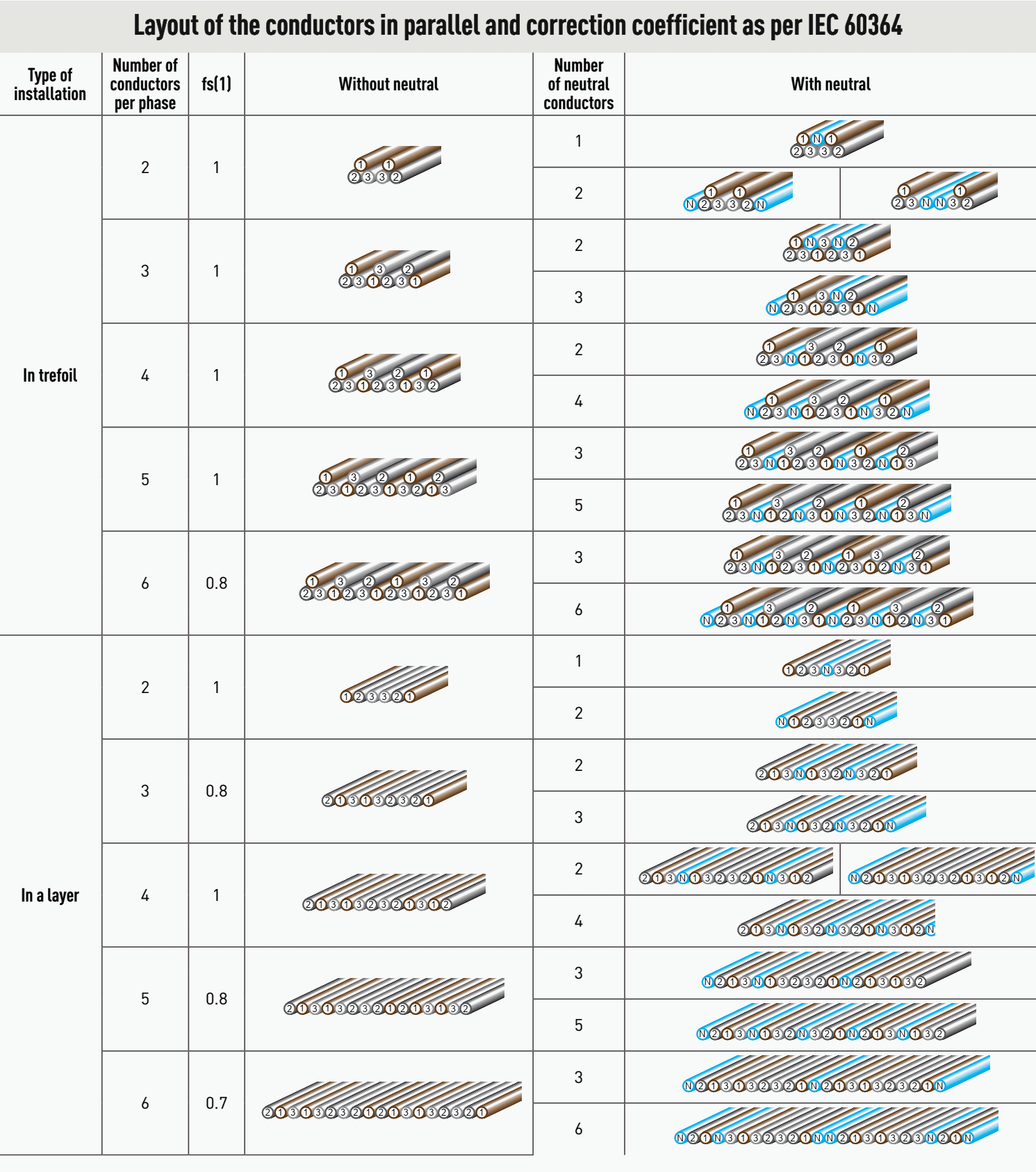
To do this, the juxtaposed layouts (single-phase circuits) or trefoil (3-phase circuits) are recommended. Those which are bundled for parallel conductors must follow strict rules (see Table 1).
It is recommended that all types of conductor (signals, controls, power, but also equipotential links and protective conductors) are routed as close as possible to structures, frames, conduits, girders and other solid items, in order to benefit from a greater reduction effect, the more effectively these solid items are linked to the equipotential system.
If multi-conductor cables are used, non-connected conductors can be linked together and connected to the equipotential circuit. They will constitute a solid structure that will reduce capacitive couplings.
2.2 Actual HF impedance of a conductor
This term covers two aspects:
- The apparent impedance of the conductor and
- The impedance of the field in which it is situated (whether or not it was generated by that conductor).
2.2.1 Apparent impedance of the conductor
The first notion is linked only to the characteristics of the conductor: its geometry (skin effect), the constituent conductor material (conductivity and magnetic permeability) but also the surrounding medium (permittivity of air) which will determine its characteristic impedance, which is a complex function of these elements but which can be simplified as:
Z = L/C at HF
For a single wire conductor, the impedance is reduced to its linear inductance and in air, this is approximately 1μh/m (1 microhenry per meter) but it should not be forgotten that, in fact, this value is linked to the notion of the conductor’s self-induction and that it only exists because a current is running through the conductor.
Unlike an electrical field, magnetism only exists if there is a movement of charges (Maxwell’s equations). In the diagram opposite, the induction B’ generated by the field I induces a self-induction current I which is opposed to the current I which originated it. Nothing prevents the selfinduction (or own mutual induction) effect. l is approximately 1 μh/m.
I’ represents the current surge on breaking which makes cutting inductive circuits difficult.
The inductance phenomenon is like a brake. the field created by the conductor generates an induction in this same conductor which will conflict with the current that created it (Lenz’s Law), which explains clearly why inductance retards the current (ϕ < 0).
2.2.2 Impedance of the field
The second notion is linked to the propagation of electromagnetic waves in the surrounding medium which will have a direct influence on the self-induction of the conductor and therefore on its inductance. If the field is modified by the propagation medium (magnetic screen, other conductor, other field, etc.), the self-induction value will also be different from the actual inductance value.
The inductance of a conductor is therefore not an absolute value but is always a positive value. It depends largely on the reciprocal influences to which the conductor is subject.
The diagram opposite shows the mutual influence of two conductors passed through by the same current but in the opposite direction. in a portion of the mutual influence space, the fields generated counteract each other, the inductions B and B’ conflict, even cancel each other out and the self-induction of the conductor is reduced.
From what we see in this diagram, we can understand clearly that the mutual effects of induction, their own or mutual, are linked to the shape of the conductors, in particular, to their ‘facing surfaces’ in the case of outward/return conductors.
2.2.3 Reduction effect from the proximity of a metal mass
In the diagram opposite, the field H must pass around the metal obstacle (in HF, the iron very quickly saturates and only the skin actually allows a field to pass). the magnetic circuit (a volume of air in this case) is lengthened and its magnetic resistance increases to the same extent.
The induction value b’ which will be coupled to the conductor will be reduced. Note, however, that this does not mean that the value of the field generated H is modified, it is simply the self-induction effect B’ which is counteracted.
3. Geometric separation of conductors and circuits
In terms of electromagnetic compatibility, a cable tray run can be compared to the routing of the tracks on a printed circuit board. A parallel which allows us to understand that there are no constant, universal rules and that most often, it is necessary to take a set of, sometimes contradictory, constraints into consideration, to determine what is the best compromise.
In the same way that the electrical separation of the supplies would be a means of limiting galvanic couplings between circuits with different intended uses, wide geometric separation would be the ideal means of avoiding capacitive and inductive couplings between conductors.
But in practice, neither one nor the other is really applicable, and in all installations, there are a number of couplings or “common electromagnetic points”.
3.1 Geometrical separation of circuits: between theory and common sense
to the extent that it is not possible to galvanically isolate circuits at their source (the power input is usually common) or at the point where they are used (in the example of communicating appliances), too systematic a separation of the conductors can lead to the creation of significant surface loops; the remedy can then be worse than the illness.
Sufficient distances should be maintained between certain circuits while following the rules for grouping together the conductors that make up these circuits.
Conductors on cable trays are subject to a set of interferences or are themselves the source of interference which depends on the frequency of the interference signal, the length of the common run and the distance between the conductors.
The coupling between conductors, generally referred to as crosstalk, is the result of several associated EMC phenomena. To this are added external phenomena such as magnetic (loop field), electrical (wire field) and mutual radiation.
Also, the nature of the conductors has a direct influence on the coupling:
- Twisted pair (type utP) to limit the inductive component of the coupling, screen (type FtP) to limit the capacitive component,
- Shielding and screen (type SFtP) to protect from external electromagnetic radiation.
The table below, based on experience, gives guide values for the principal installation and electromagnetic pollution situations.
Table 2 – Minimum recommended cohabitation distances d (in mm)
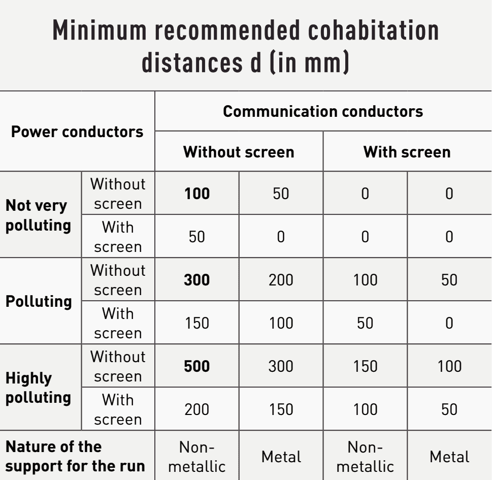
3.2 Cohabitation lengths
In practice, the minimum cohabitation distance depends on the length of the shared run. The more circuits cohabit over a long run (several dozen metres), the more it is important to comply with this distance.
In fact, the frequency bandwidth that characterises the coupling between conductors is directly proportional to the wavelength of the frequencies in question and therefore to the length of the cohabitation.
For medium frequency disturbances (typically < 100Mhz), the critical cohabitation length will be of the order of around ten meters. At a distance of 1 m it will fall to disturbances at a frequency of 1 gigahertz. Also, high-frequency disturbances are predominantly electrical and attenuate far less quickly (in 1/d2) than low frequency, predominantly magnetic disturbances (in 1/d3).
3.3 Separation of certain devices
Some devices (fluorescent lighting, motors, welding sets, arc and induction furnaces, etc.) constitute local sources of pollution and cable trays and trunking should be kept away from them and vice versa.
Contrary to what we read in certain publications, there is no ideal separation distance. Everything depends on the level of pollution, the sensitivity of the circuits and the frequencies involved.
The values in bold in the Table 2 opposite may be used as a guide.
4. Electromagnetic screening of cable trays and prefabricated trunking
By its nature cable tray does not constitute an ideal Faraday cage. And it is undoubtedly slightly ridiculous to want to guarantee electromagnetic screening performance for this type of product. For this to be the case their metal enclosure would have to be complete and continuous, with cable outlets themselves in continuity with the enclosure and joins between sections completely sealed against electromagnetic leaks.
The nature of the support for the run then has only limited importance. in all cases, the correct layout of the conductors with a view to limiting coupling does, of course, apply.
Metal trunking with a lid provides some protection against radiated fields but it remains limited (approximately 40dB) and does not go beyond the area of frequencies below 100 Mhz.
It is nevertheless of value to use them for additional local protection (passing through a polluted zone close to a machine). Except with closed conduits or metal trunking, obtaining a constant level of screening throughout an entire installation is practically impossible.
4.1 Magnetic field emissions
Cable runs constitute sources of magnetic field emissions that become more and more significant as the current conveyed increases. In most installations on traditional wire or sheet metal cable tray, there is nothing that can be done to limit associated magnetic fields.
In fact, they are produced by the layout of conductors that have to comply with certain positioning rules relating to electrical aspects (permissible current depending on mutual inductances) or electromagnetic aspects (couplings).
Unlike devices or machines which have a local effect and to which access can be limited to qualified personnel, power transport throughout buildings produces radiation along its length, including in areas that are unprotected, even those where the public has access.
Radiated magnetic fields must now be controlled, which adds a new dimension to the choice of equipment used to convey energy. This can be a determining factor in the use of cable tray or prefabricated trunking.
Sources: Transport and distribution inside LV installation by Legrand

Hi Edward, Very informative thanks a lot. Kindly can you clarify for LV system,
if IEC regulations allows more than one multi-core armoured cables(3 phase neutral) grouped in two layers(one top of the other) ? in a perforated cable tray. if no why ? any specific methods to follow ? if yes what is the correction factors to be considered ? thanks in advance.
A super good document both for covered areas and uncovered areas. Even more when no.of cables per phase are high, should bundle eventually at common distance (one cable of each phase bundled together). Please correct me if am wrong here.
Good article , very helpful
Very helpfull and perfect information.
Thanks a lot to Mr. Edvard Csanyi.
👍👍👍👍👍
Very Informative Article…Thanks
Excellent article, thanks for posting. The same topic would be interesting but, in underground pipes or magnetic and non-magnetic conduits. thank you so much.
Excellent and very helpful article .
Excellent article. Congratulations Mr. Edvard.