
Estimated Study Time: 27 minutes
Troubleshooting Motors
Generally, electric motors are highly reliable (except when they’re not!) machines that require little maintenance. In practice, often even this little care is neglected, and problems with motors come ‘unexpected’ like a hurricane. Let’s discuss the eleven most common problems in electric motors, their remedy and the most important maintenance checks.
 General problems in electric motors and their remedy
It is essential to perform preventative maintenance to prolong motor lifespan and minimize the risk of unexpected outages and production losses.
Insulation failure and bearing failure are the two predominant causes of motor malfunctions, frequently preventable with basic maintenance.
Generally speaking, motors that are continually used under typical service circumstances should have an overhaul every five or six years. However, more frequent overhauls are necessary for motors that operate in harsher environments. For motors with reduced operating hours, the time interval may be correspondingly prolonged.
This discussion is solely to the most general categories of problems.
- Troubleshooting Motor Problems and Solutions:
- Problem #1 – Bearings make a churning noise or overheat
- Problem #2 – Creaking and harsh motor noises
- Problem #3 – Motor not picking up speed
- Problem #4 – Motor not taking up load
- Problem #5 – Metallic Shorting links not removed
- Problem #6 – Motor takes longer to pick up
- Problem #7 – Motor trips and/or fuses blow during start
- Problem #8 – Motor vibrates
- Problem #9 – The motor makes rumbling noise and the stator current fluctuates
- Problem #10 – Motor is submerged in water
- Problem #11 – Motor Cast iron body, feet or ribs broken
- Important checks at the time of commissioning
- Maintenance of electric motors and their checks
- Maintenance of motor bearings
- Attachment (PDF) 🔗 Download ‘The Control of Industrial Motors: Schematic Diagrams and Troubleshooting’
1. Troubleshooting Motor Problems
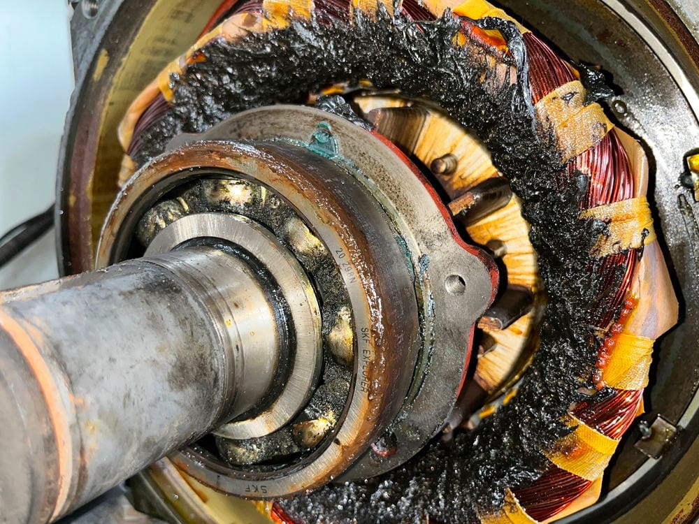
Problem #1 – Bearings make a churning noise or overheat
Check condition and level of grease as well as any skin effects or watermarks on the races, balls or rollers. If there are watermarks, the bearings should be replaced. Otherwise wash and regrease them.
Many engineers believe that a bearing that is operating flawlessly should be silent. The physics of a rolling bearing’s action naturally produce sound. This intrinsic noise results from several physical interactions that are inevitable, even in optimal settings.
Yes, but… A frequent misunderstanding is that more grease is necessarily better when it comes to bearings. Overheating, broken seals, and bearing failure are some of the serious issues that can arise from using excessive grease.
Figure 1 – Bearings often make a churning noise or overheat
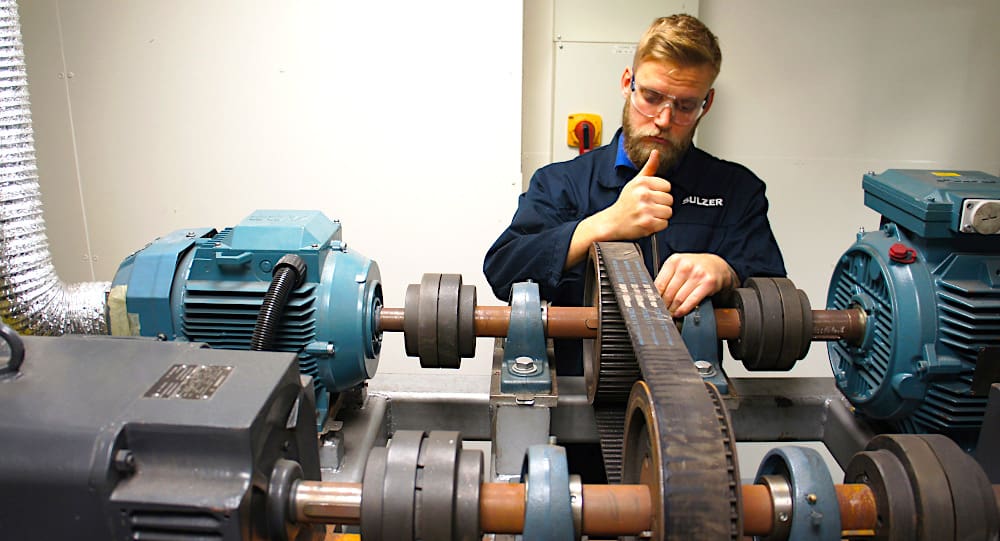
Problem #2 – Creaking and harsh motor noises
For creaking and harsh noises, check for misalignment and belt tension. Proper alignment of the motor and load is critical under real-world operating conditions and temperatures. When the temperature changes, even machines that are perfectly aligned at ambient temperature might become severely misaligned as a result of deformation or other forms of thermal growth.
Once the driven machine and motor have reached their maximum operating temperatures, you should inspect the alignment and make any required adjustments.
Figure 2 – Checking motor belt tension
Problem #3 – Motor not picking up speed
This problem could indicate a serious problem. What should you do?
Check #1 – Phases
You should check all phases for supply continuity.
Check #2 – Voltage
You should check the voltage.
Check #3 – Starter connections
Check the starter connections and contacts in all three phases. Also check proper contacts and brush pressure in slip-ring motors. If these are satisfactory and the motor still does not pick up, check the suitability of the motor for the type of load and switching method.
Check #4 – Fault in the switching device
Sometimes, the switching device may not be functioning properly. To give an instance, one 150 h.p. squirrel cage motor was selected for a centrifugal air compressor.
The motor starting torque was adequately chosen to start the compressor through an auto-transformer starter with a 40% tapping. The motor started but locked up somewhere in the middle of the full speed and did not-accelerate further.
In fact the auto-transformer was faulty or not properly connected so that it was producing only 25% voltage instead of 40% in the secondary circuit thus seriously affecting the torque and the motor’s starting performance.
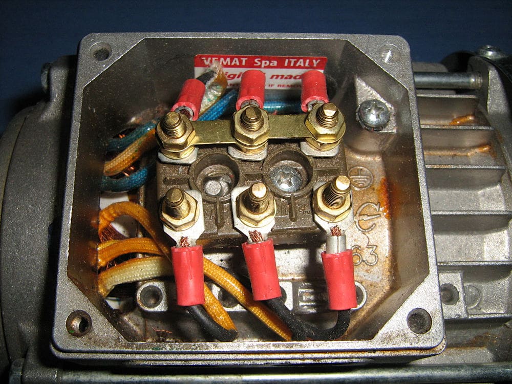
Problem #4 – Motor not taking up load
Motor not taking up load may be due to incorrect stator connections. In general, motors of 3 h.p. and above, except medium voltage motors, are wound for delta connections and all the six terminals are located in the terminal box to facilitate Y/Δ starting.
These terminals are connected in delta through metallic links. See Figure 3.
Figure 3 – Terminals inside a terminal box
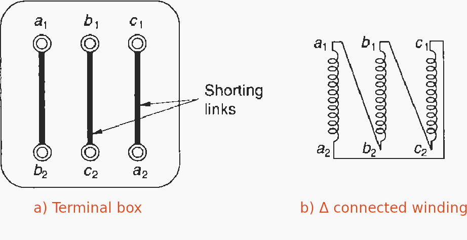
If the motor is inadvertently connected in star, each motor phase will receive only 1/√3 times the rated voltage. This will reduce the torque to one third of the rated torque which may not be adequate to pick up the load.
It may even damage the windings if the motor remains energized for a while due to excessive load current (I2R losses).
Problem #5 – Metallic Shorting Links Not Removed
While connecting a delta-wound motor through a Y/Δ starter, the metallic shorting links MUST be removed. Otherwise the starter will have a dead short-circuit at the motor terminal box and may burn the starter, damage the motor terminal box and even line cables.
Figure 4 – Motor terminal box

Problem #6 – Motor takes longer to pick up
When conditions #3 and #4 above have been checked but this problem still arises, then motor selection may not be appropriate for the type of load or the method of switching. For example, a ball mill at a thermal power station required a 75 kW motor employing a Y/Δ manual switching (an old installation).
The method of switching was overlooked at the time of motor selection. The motor burnt during the start while the starter was still in the star position. The stator was found to be completely charred and the rotor damaged to the extent that its short-circuiting rings also melted due to excessive starting heat and some molten metal was scattered over the stator overhangs causing extensive damage.
The reasons for such a failure can be as follows:
Reason #1
The starter was manually operated and thus the changeover time, from star to delta, largely depended upon the skill of the operator, who may have been unaware of the implications of a longer starting period in the star position.
Moreover, on load, the starting heat in a Y/Δ starting is much more than on a DOL starting.
Reason #2
The fuse rating, if used before the starter, may have been inadvertently high, inconsistent with the thermal withstand capacity of the motor. Thus the fuse did not blow which would have protected the motor from such severe and persistent overloading.
Watch Video – Selection of a Fusible Disconnect Switch for a Motor Load
Reason #3
The over-current relay selection or its setting may not have been appropriate, otherwise the starter would have tripped under such a faulty condition.
Selection and over-current setting of the relay should have been consistent with the motor’s thermal capacity.
Reason #4
A ball mill requires a high starting torque to accelerate its heavy masses. In the star position, the motor torque diminishes to one third the starting torque as on DOL. The mill would take a long time to accelerate and the ampere meter would show almost a constant starting current.
The operator, possibly also judging the speed of the ball mill, may have paused in the star position before changing it over to delta but by then the motor had failed. Thus, it was a wrong application of the switching device for the type of load.
For critical applications and for larger motors it is essential to check the speed-torque requirement of the load with that of the motor.
Suggested Reading – Star-delta starting used with large horsepower motors
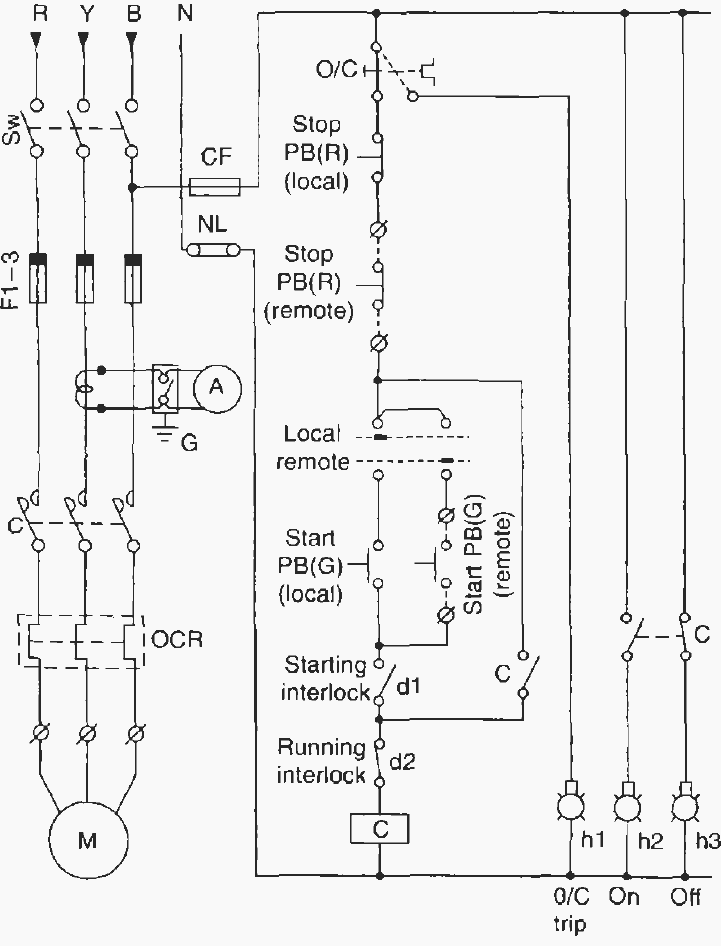
Problem #7 – Motor trips and/or fuses blow during start
The reasons for such a failure can be as follows:
Reason #1
Check selection of fuses for the type of load and switching. Perhaps they are under-rated for the starting inrush current and its duration.
Reason #2
Supply voltage may be low, causing the motor to take longer to start.
Reason #3
Starter relay selection or relay setting may not be matching the starting requirements. The relay thermal characteristics must match motor characteristics. In heavy drives with prolonged start times the relay may not operate if it is not properly selected.
The most common practice is to provide a CT-operated thermal overload relay. The CTs have a low saturation point. In the event of a high starting current, they become saturated at two to three times the full load current and bypass the excessive starting kick through the relay and thus avoid a false trip during a prolonged start.
Figure 5 – DOL starter with provision for remote control and starting and/or running interlocks
Problem #8 – Motor vibrates
A motor already tested at the manufacturer’s works for vibration limits, may still appear to have more vibrations at site during operation.
This may be due to the following reasons:
Reason #1
The foundation bed or the structure on which the motor is mounted is not rigid, is tilted or is uneven. Tighten foundation bolts and check for proper alignment of the motor and the drive. Make the foundation or structure as rigid as possible.
Reason #1
Single phasing, in which case the motor may make a humming noise and cause vibrations due to uneven flux distribution.
Reason #2
Bearing-end play may also cause such vibrations.
Reason #3
It is possible that the driven equipment to which the motor is coupled has a higher vibration level than the motor, resulting in quantum imbalance and more vibrations than when the motor was tested.
All attempts must be made, to bring the vibration level of the drive and the driven system within the limits as prescribed in Table 1 below.
Table 1 – Limits of vibration levels when measured in a state of free suspension
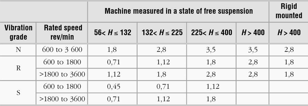
Important Notes:
- If no grade is specified, machines complying with this standard shall be grade N.
- Grade R machines are frequently ordered for machine-tool drives. Grade S machines are in use as drives for special machines with extreme vibration requirements. Grade S is applicable only to machines with shaft heights ≤ 400 mm.
- For machines requiring values lower than those given in Table 1, it is recommended to select values from the series 0,45; 0,71: 1,12; 1,8 and 2,8 mm/s.
- For machines with H > 400 mm, both methods of mounting are applicable. Unless otherwise agreed, the choice of the method will be made by the manufacturer.
- Manufacturer and purchaser should take into account that the instrumentation can have a measurement tolerance of ±10%.
- A machine, which is well balanced in itself and of a grade conforming with the table, may exhibit large vibrations, when installed in situ, arising from various causes, such as unsuitable foundations, reaction of the driven machine, etc.Vibration may also be caused by driving elements with a natural oscillation frequency very close to the excitation due to the small residual unbalance of the rotating masses of the machine. In such cases, checks should be carried out not only on the machine, but also on each element of the installation.
- The shaft height of a machine without feet, or a machine with raised feet, or any vertical machine is to be taken as the shaft height of a machine in the same basic frame, but of the horizontal shaft, loot-mounting type 8.2.
Problem #9 – The motor makes rumbling noise and the stator current fluctuates
The rotor circuit may be broken and should be repaired. If the motor also overheats, there may be an inter-turn fault or a short-circuit between the phases. Detect these and rectify if possible, otherwise rewind the motor.
Problem #10 – Motor is submerged in water
If heavy rain causes a flash flood at the site of installation, the motor may be submerged in water for some time. A reasonably good motor, with good insulation impregnation and baking, can be washed and dried, to work again.
Dismantle the motor, take out the rotor and bearings. Wash the stator and rotor with clean water to remove all the mud and silt. Pad it dry with cloth. Blow warm air over the stator and the rotor and heat them gradually.
As a precaution, insulation resistance must be checked before a restart after a long shutdown, even in temperate conditions.
Unless they show permanent watermarks or rust or scratches, the bearings can also be washed dry and regreased.
Good Reading – Mastering schematic drawings: Analyzing seal-in contacts in motor control circuits
Mastering schematic drawings: Analyzing seal-in contacts in motor control circuits
Problem #11 – Motor Cast iron body, feet or ribs broken
Cast iron body, feet or ribs etc. found broken or cracked during transit or otherwise. Replacement of the motor in such cases may not be practical. However, using the motor may not be advisable in view of a weaker foundation and insufficient cooling. In such cases the broken parts can be welded using cast iron electrodes.
Cracks, however, cannot be remedied. Unless the cracks are wide and may cause extensive damage during operation, the body may still not require replacement.
Minor cracks, however, which do not impair the motor’s performance or cause development of further cracks, may be compromised.
Further Study – Troubleshooting the most typical winding problems of three phase electric motors
Troubleshooting the most typical winding problems of three phase electric motors
2. Important checks at the time of commissioning
- Clean up the motor.
- Check all the components for their positioning and tightness.
- Check for pre-lubrication / grease and its monitoring attachment (provided in large machines).
- Check for free rotation of the rotor.
- Check for motor grounding.
- Check for winding insulation.
Additional checks for large motors:
- Check for proper connection and circulation of fluid or gas in the coolant circuit.
- Check for satisfactory operation of auxiliary oil pump and fan.
- Check all safety devices such as temperature sensors in the windings and the bearings, PTC thermistors, vibration probes, space heaters and coolant circuit, for their correct fitting, wiring and functioning of the alarm, annunciation and tripping circuit of the protective switchgear.
- Check for satisfactory functioning of all gauges, indicators and recorders.
- Check for bearing insulation.
- Check for bearing housing grounding.
- Check for winding insulation by polarization index and dissipation factor.
Further Study – Mastering Motor Control Center (MCC): Wiring diagrams & equipment
Mastering Motor Control Center (MCC): Wiring diagrams and equipment from zero to hero
3. Maintenance of electric motors and their checks
Only important aspects have been considered here:
Advice #1
Protected-type motors, located in dusty environments, should be blown out periodically with clean and dry air. Replace the motor, if possible.
Advice #2
Check the protective equipment for any worn parts or contacts and their tightness.
Advice #3
Check the condition of the cable insulation, its termination and jointing. Motor connections should always be made through cable lugs to ensure a proper grip as shown in Figure 6. A poor cable termination will mean arcing and localized heat and may lead to joint failure.
Figure 6 – Motor terminal box connection
Advice #4
For oil-filled control equipment such as auto-transformer starters, insulating oil should be checked periodically for its insulating properties. Leading manufacturers of this equipment indicate the number of switching operations under different conditions of load and fault, after which the oil must be replaced and these must be followed.
Advice #5
Each electric motor and connected control gear is grounded separately at least two points. The ground resistance should be checked to ensure continuity of ground conductors. Refer to this technical article for more details on grounding requirements.
Advice #6
Insulation resistance of the motor windings between phases and phase to ground should be checked and made up in the event of deficiency.
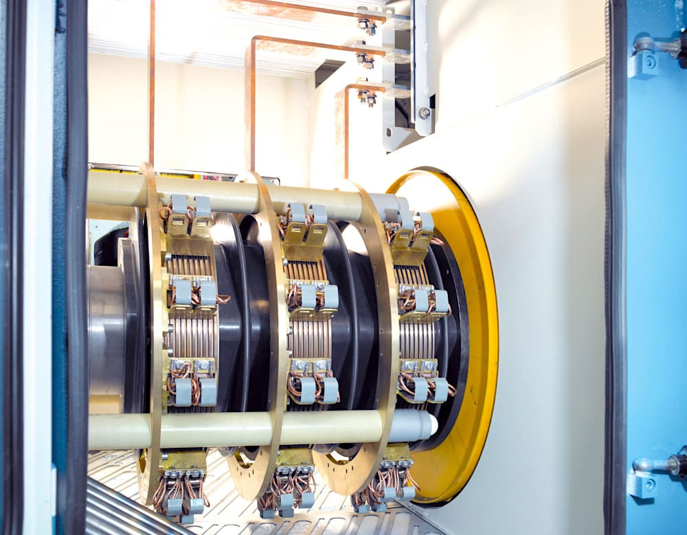
Advice #7
Slip-ring motors need a regular and meticulous check of brushes, brush holder unit and slip-rings for cleanliness, accurate contacts, brush curvature, wear and tear of slip-rings and arcing (Figure 7). The following procedure may be followed:
- Spring for pressure to be maintained around with 150-200 g/cm2 for proper to contact of the brushes with the slip-rings.
- Cleanliness of slip-rings and the brushes.
- Slip-rings, if roughened by arcing, must be cleaned with fine glass paper, having a similar curvature to the rings using a wooden block on which the glass paper can be wrapped. Emery cloth should not be used.
- When replacing with the new brushes, the new brushes must be first ground to acquire a curvature similar to that of the rings.
- Brush lifting and short-circuiting devices can be employed for motors required to run continuously for a long period to minimize wear and tear of slip-rings and brushes. However, when speed control is required or switching operations are frequent, continuous contact brush gear assembly must be employed.
Figure 7 – Slip-ring assembly with brush lifting and short-circuiting gear
4. Maintenance of motor bearings
Grease may leave skin effect on the races of the bearings if the motor is stored idle for a long period. This may cause noise during operation and overheating of the bearings. After a long period of storage grease may also dry and crack, and produce these effects.
To detect this, bearing covers may be opened and the condition of the grease and any skin effects checked. If such marks are visible, the bearings must be taken out and washed thoroughly in petrol or benzene to which is added a few drops of oil, and then re-greased with a recommended grade and quantity of grease.
Quantities of grease above recommended levels may cause heat the same way as quantities below recommended levels.
Suggested Course – Motor Control Schematics Course For True Engineers

5. Attachment (PDF)
The Control of Industrial Motors: Schematic Diagrams and Troubleshooting
Download: The Control of Industrial Motors: Schematic Diagrams and Troubleshooting (for premium members only):
References:
- Industrial Power Engineering & Applications by K.C. Agrawal
- Rotating electrical machines: Part 14: Mechanical vibration of certain machines with shaft heights 56 mm and higher (Measurement, evaluation and limits of vibration)
Related electrical guides & articles


Edvard Csanyi
Hi, I'm an electrical engineer, programmer and founder of EEP - Electrical Engineering Portal. I worked twelve years at Schneider Electric in the position of technical support for low- and medium-voltage projects and the design of busbar trunking systems.I'm highly specialized in the design of LV/MV switchgear and low-voltage, high-power busbar trunking (<6300A) in substations, commercial buildings and industry facilities. I'm also a professional in AutoCAD programming.
Profile: Edvard Csanyi
