
Estimated Study Time: 9 minutes
Emergency and standby power systems
Emergency and standby power systems are generally designed into the over-all electrical system for one of the following two reasons:
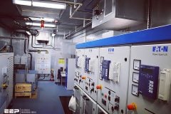
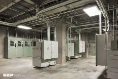
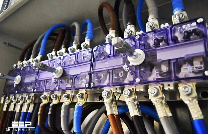 Single line diagrams of emergency and standby power systems with automatic transfer switch (ATS) (on photo: ATS selects between the normal power grid and emergency generator; credit: interdc.nl)
- Legal Requirements – As required by the NEC, NFPA 101, NFPA 99 and other local, state, and federal codes and requirements. These are concerned with the safety of human life, protection of the environment, etc.
- Economic Considerations – Continuous process applications often require a continuous source of electrical power to avoid significant economic loss. In some cases even a momentary loss of power can be disastrous.
Various ways of arranging emergency and standby power systems exist. The most common arrangements are given here.
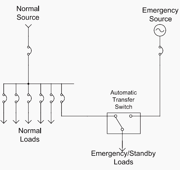
1. Basic arrangement – radial system
The most basic arrangement for an emergency or standby power system is shown in figure 1. This can be recognized as an extension of the single-source radial system, with the transformer omitted.
The transfer switch transfers the emergency / standby loads to the alternate source upon failure of the normal source.
This simple system may be expanded to the other system types like expanded radial systems with:
- 1 utility source and a single primary feeder
- 1 utility source and multiple primary feeders or
- 2 utility sources and multiple primary feeders.
Go back to most common arrangements ↑
2. More complex systems
The basic arrangement from figure 1 may be extended to the other system arrangements. For example, the secondary-selective system could be equipped with an emergency system as shown in figure 2:
In figure 2, the emergency / standby load at the bottom of the figure will always be supplied by one of the normal sources if possible, and by the generator(s) if not. This will avoid the generator starting time for this load if one utility source were to fail. The two emergency / standby loads in the middle of the figure will be supplied by their respective switchboard busses or by the emergency source.
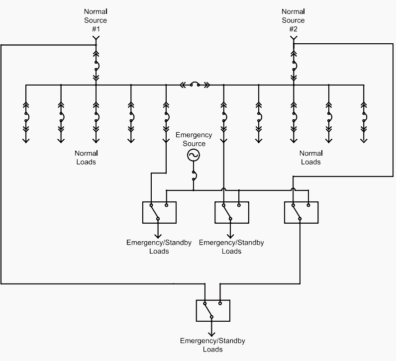
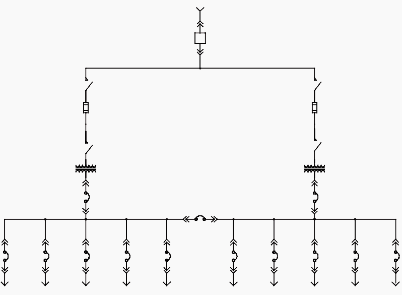
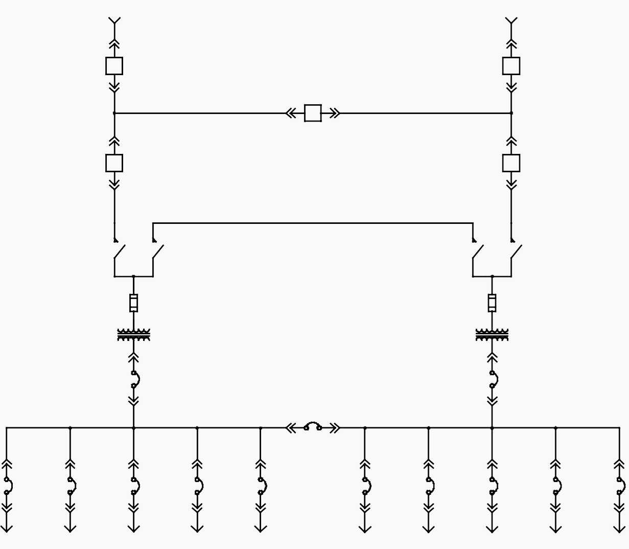
Emergency / standby systems are not limited to the low voltage level. For example, the primary selective / primary loop / secondary selective system can be expanded to include an emergency system, as shown in figure 3:

In figure 3 above there is a great deal of flexibility in the system operation. However, instead of automatic transfer switches metal-clad switchgear is used increasing the complexity of the system.
Go back to most common arrangements ↑
3. Hospital arrangements
NFPA 99 and the NEC have very unique requirements for the design of a hospital emergency system. The emergency system is classified into the essential electrical system and the emergency system itself.
Emergency system is “a system of circuits and equipment intended to supply alternate power to a limited number of prescribed functions vital to the protection of life and safety”. The emergency system is a part of the essential electrical system.
The minimum arrangement, for hospitals 150 kVA or less, is shown in figure 4a. The minimum requirement over 150 kVA is shown in figure 4b.
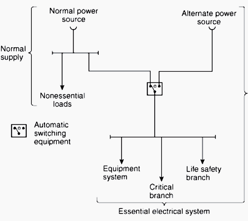
The essential electrical system supplies the equipment system, defined as “a system of circuits and equipment arranged for delayed, automatic, or manual connection to the alternate power source and that serves primarily 3-phase power equipment”.
The emergency system also supplies the critical branch, which is “a subsystem of the emergency system consisting of feeders and branch circuits supplying energy to task illumination, special power circuits, and selected receptacles serving areas and functions related to patient care”.
For hospitals of 150 kVA and less the equipment system, life safety branch, and critical branch may be on the same transfer switch. Note that the transfer switch(es) for the equipment system above 150 kVA is required to be delayed (figure 4b).

Go back to most common arrangements ↑
Automatic transfer switch – ATS
An automatic transfer switch is defined as “self-acting equipment for transferring one or more load conductor connections from one power source to another”. The automatic transfer switch is the most common means of transferring critical loads to the emergency / standby power supply.
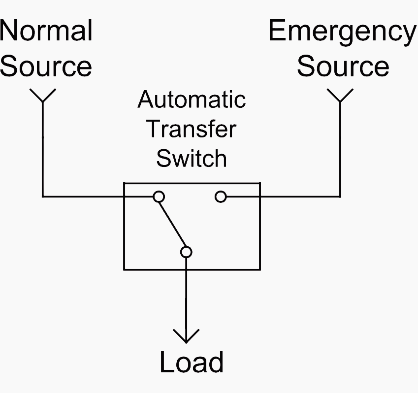
An automatic transfer switch consists of a switching means and a control system capable of sensing the normal supply voltage and switching over to the alternate source should the normal source fail. Automatic transfer switches are available in ratings from 30-50 A, and up to 600V.
Automatic test switches with adjustable pickup and dropout setpoints and integral testing capability are generally preferred. An automatic transfer switch is generally an open-transition device that will not allow paralleling of the two sources. Manual versions of transfer switches are also available.
A single line representation of an automatic transfer switch is shown in figure 5 above.
Go back to most common arrangements ↑
Anatomy of an Automatic Transfer Switch (VIDEO)
Go back to most common arrangements ↑
Reference // Emergency and Standby Power Systems by Bill Brown, P.E., Square D Engineering Services
Related electrical guides & articles


Edvard Csanyi
Hi, I'm an electrical engineer, programmer and founder of EEP - Electrical Engineering Portal. I worked twelve years at Schneider Electric in the position of technical support for low- and medium-voltage projects and the design of busbar trunking systems.I'm highly specialized in the design of LV/MV switchgear and low-voltage, high-power busbar trunking (<6300A) in substations, commercial buildings and industry facilities. I'm also a professional in AutoCAD programming.
Profile: Edvard Csanyi

I am interested, to know more about you and also please can you send me more tutorials for electrical drawings and ATS installation.
By looking your engineering tutorials i learning and I need more
Very informative and insightful pieces of information. Thank you Edvard and EEP for a job well done.
at present I am working in Kuwait as Electrical Technicians and we having maintenance of Generators, ats like Cummins and Caterpillar. I am India.
Thanks for explained Manuel.
Is MV (13.8KV) standby generator permitted for the hospitals design as per UK code?
Can we have a contractor which performs the function like relay
thank you for this explanations. can you please help me to design of single line diagram of a panel box has two sources one from utility power and the other from diesel generator using transfer automatic switch.
Want to have an interactive model of your electrical network, https://www.youtube.com/watch?v=euVTGipVoTU
Awaiting for Some load distribution network for international airport…
Very simple high-level overview of a lower KE or kVA installation of SEP.
In the diagram showing the standby power especially for the hospitals I would anticipate that the higher requirements for the hospitals, would have either a static or rotary UPS system as an alternate source for the super critical load, to include automatic transfer switches that have the ability to synchronize to SEP and perform an overlap transfer. (For maintenance or load testing of inductive loading on the SEP without the client being affected).
Of course depending on the system and devices connected to the emergency circuits like the EKG machines are in critical care equipment, if they all had battery backup locally, then it would be OK as long as The connected loads or equipment could last for at least 15 minutes without emergency power. Typically, you would know if your generator or alternate power source did not ramp up or a transfer switch failed to transfer within the first 30 seconds of a power outage.
Again very simple concept in the video high-level overview without getting too technical is good for the clients and The students learning chapter 1 on basic concepts. I’m sure there’s another video that goes into greater detail on the Dynamics of all types of transfer switches in inhibit transfer systems in the more complex UPS systems. A standard design for the installation of a generator and a transfer switch for critical facilities that have on-site staff 24 seven in my opinion at least, where I have installed similar basic momentary switches or toggle switches tied to the transfer inhibit, thus enabling the on-site staff to verify with the local utilities first even if power has returned there’s no guarantee that it’s not going to go out again so the installation of a two dollar switch to inhibit every event or transfer back to normal, unless of cours, normal was available and the engine or standby power was not, then it would fail to the normal power. It’s just the standard that I have used over many years with 100% success, to inhibit an automatic retransfer with my 24 seven staffed facilities.