
Estimated Study Time: 20 minutes
Introduction to Overhead Conductors
Overhead conductors are widely used in electrical substations to interconnect primary equipment such as circuit breakers, disconnectors, current transformers, and busbars. Although these conductors often span relatively short distances compared to transmission lines, their selection remains a critical engineering task.
 Four Essential Engineering Studies for Selecting Overhead Conductors in Substations
A substation conductor must safely carry the continuous operating current, withstand the thermal stress caused by short-circuit currents, maintain acceptable mechanical tension and sag under varying environmental conditions, and resist the electrodynamic forces produced during fault events.
In practice, selecting an aerial conductor cannot rely solely on nominal current ratings or manufacturer catalogues. Instead, a series of technical studies must be performed to verify that the conductor meets both thermal and mechanical requirements throughout its operating life.
- Ampacity calculations
- Verification of short-circuit thermal withstand capability
- Sag and tension analysis
- Evaluation of electrodynamic forces during short circuits.
This article presents the key engineering studies required for the proper selection of overhead conductors in substations and explains the purpose and methodology of each verification step.
Together, these analyses form the foundation of a reliable and standards-compliant substation conductor design.
- Ampacity Calculation (IEEE Std 738)
- Short-Circuit Thermal Withstand Verification
- Sag and Tension Study
- Short-Circuit Mechanical Forces (IEC 60865-1)
- Conclusion
- Video Course 🎥 ETAP Power System Design and Analysis Course: Learn To Resolve Power System Issues
- Attachment (PDF) 🔗 Download ‘Tutorial Guide to Control and Automation of Electrical Power Distribution Systems’
1. Ampacity Calculation (IEEE Std 738)
After determining the maximum operating current from the load flow study, the next step is to verify that the selected conductor can safely carry this current under the actual environmental conditions of the installation site. This verification is performed through an ampacity calculation, which determines the maximum continuous current that a bare overhead conductor can carry without exceeding its allowable operating temperature.
Unlike cable systems installed underground, the thermal behavior of bare conductors installed in air is strongly influenced by environmental parameters. Therefore, the current-carrying capacity of an overhead conductor cannot be considered a fixed value from a manufacturer’s catalogue.
Instead, it must be calculated by considering the thermal balance of the conductor under the specific site conditions.
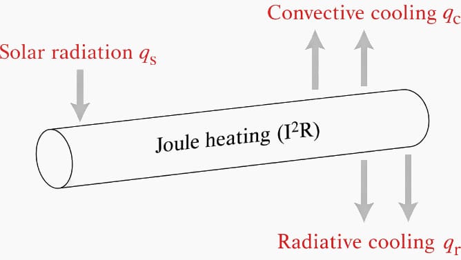
The main sources of heat input are:
- Joule heating (I²R losses) caused by the electrical current flowing through the conductor
- Solar heating, which depends on the solar radiation intensity and the conductor’s absorptivity
- Heat is dissipated through two primary mechanisms:
- Convective cooling, mainly influenced by wind speed and air properties
- Radiative cooling, which depends on the conductor temperature and surface emissivity
Figure 1 depicts the balance between Joule heating, solar heating, and cooling by convection and radiation
Figure 1 – Thermal balance of a bare overhead conductor (IEEE Std 738)
Environmental parameters such as ambient temperature, wind speed, solar flux, altitude, and conductor surface characteristics significantly affect this thermal balance.
As a result, the calculated ampacity can vary considerably depending on the geographic location and climatic conditions of the substation.
The selected conductor must therefore provide sufficient ampacity under the worst expected environmental conditions, ensuring that the maximum current determined from the load flow study can be carried safely during continuous operation.
Good Reading – Five Construction Issues That Do Not Follow the Engineering Design
Five Construction Issues That Do Not Follow the Engineering Design (And Why They Matter)
2. Short-Circuit Thermal Withstand Verification
In addition to carrying the continuous operating current, the selected conductor must also withstand the thermal stresses caused by short-circuit currents. During fault conditions, very high currents may flow through the conductor for a short duration until the protection system clears the fault.
This current produces significant Joule heating, which can rapidly increase the conductor temperature.
If the conductor temperature rises beyond acceptable limits, the aluminium strands may experience annealing, leading to a permanent reduction in mechanical strength. For this reason, it is necessary to verify that the conductor can tolerate the thermal energy generated during a short circuit without exceeding the permissible temperature limits.
The verification is based on the following relationship:
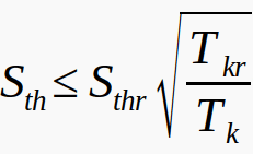
where:
- Sth is the thermal equivalent short-circuit current density, calculated from the thermal equivalent short-circuit current and the effective aluminium cross-section of the conductor
- Shtr is the rated short-time withstand current density obtained from IEC 60865-1
- Tkr is the rated short-time duration associated with the withstand capability
- Tk is the actual duration of the short-circuit current, typically defined by the protection clearing time
The short-circuit current itself is usually obtained from a fault current study performed according to IEC 60909. Once the thermal equivalent short-circuit current is known, the corresponding current density can be calculated and compared with the permissible value defined by the standard.
This verification ensures that the conductor will not experience excessive temperature rise during fault conditions and that its mechanical and electrical properties remain within acceptable limits after a short circuit event.
Video Lesson – Overhead line calculation
3. Sag and Tension Study
After verifying the thermal capability of the conductor, the next critical step is the sag and tension analysis, which determines the mechanical behavior of the conductor under different environmental and operating conditions. In substations, this analysis is particularly important for busbar conductors, where spans between gantries can be relatively large and the resulting mechanical tensions may be significant.
The purpose of the sag and tension study is to determine the conductor sag, horizontal tension, and support loads for various loading conditions. These calculations are typically performed according to methodologies described in CIGRÉ Technical Brochure 324, which provides detailed guidance for the mechanical analysis of overhead conductors.
The mechanical state of the conductor is influenced by several parameters, including:
- Conductor weight and mechanical properties,
- Span length and geometry,
- Ambient temperature,
- Wind pressure, and
- Ice loading (in regions where icing conditions may occur).
Therefore, the analysis must consider multiple loading scenarios, including combinations of wind and ice loads, which can significantly increase the effective weight of the conductor and therefore the tension in the span.
These environmental conditions represent critical design cases and must be considered in order to ensure the mechanical reliability of the installation.
Figure 2 – Ice accumulation on substation conductors significantly increases the mechanical load on the span and must be considered in sag and tension calculations.

Another factor that increases the complexity of sag and tension calculations is the presence of inclined spans, which are common in substations where the conductor is supported by structures at different elevations. In such cases, the classical level-span equations cannot be directly applied, and the conductor profile must be calculated using catenary equations adapted for inclined spans.
This typically requires an iterative solution, since the conductor length changes with temperature and loading conditions.
At higher temperatures, the conductor expands and the sag increases, which may affect electrical clearances within the substation. The resulting tension values at the supports are not only important for the conductor itself but must also be considered in the structural design of the supporting steel gantries and their foundations.
The horizontal and vertical forces derived from the sag and tension study are therefore used as input loads for the static structural analysis of the substation structures, ensuring that both the conductor system and the supporting infrastructure are designed to withstand all expected operating and environmental conditions.
Further Study – Analysis of voltage sags in power distribution networks
4. Short-Circuit Mechanical Forces (IEC 60865-1)
When a short circuit occurs in a substation, the electromagnetic interaction between current-carrying conductors causes dynamic mechanical effects on the span. According to IEC 60865-1, the behaviour of horizontal conductors during a fault must be analysed by evaluating several distinct forces and movements that occur throughout the short-circuit event.
The standard distinguishes between different tensile forces acting on the conductor at various stages of the fault:
Dynamic tensile force during the fault (Fₜ,d)
This force occurs due to the swing-out of the conductor during the short circuit. The electromagnetic interaction between phases causes the conductors to move away from their initial position, which increases the tension in the span.
Residual tensile force after the fault (Ff,d)
After the short circuit is cleared, the conductor returns toward its original position. However, the conductor may experience additional tension due to the modified sag and elongation of the conductor, resulting from the dynamic movement during the fault.
Pinch force in bundle conductors (Fp,i,d)
In bundle configurations, the subconductors interact electromagnetically during the short circuit. This interaction produces pinch forces, which tend to pull the subconductors toward each other. These forces can be significant and must be considered when designing spacers, clamps, and bundle hardware.
In addition to the tensile forces, the standard also requires evaluation of the movement of the conductor within the span, which may affect electrical clearances:
Movement of the conductor within the span
Horizontal displacement of the conductor (bₕ)
During the short circuit, the conductor may swing outward from its initial position. This horizontal movement must be calculated in order to determine the maximum displacement of the span.
Watch Video – Busbar Forces
Minimum air clearance between conductors (aₘᵢₙ)
As adjacent conductors move during the fault, the distance between them may decrease. It is therefore necessary to verify that the minimum clearance remains acceptable during the conductor swing-out.
For flexible conductors installed in substations, the mechanical stresses resulting from line-to-line faults and balanced three-phase faults are generally comparable. However, line-to-line short circuits often represent the most critical condition, since the adjacent conductors carrying fault current tend to move toward each other, resulting in reduced phase spacing. For this reason, the swing-out displacement and associated forces are typically evaluated for line-to-line fault conditions.
It is also important to note that the calculated tensile forces:
- Fₜ,d,
- Ff,d, and
- Fp,i,d
include the effect of the existing static tension caused by the conductor weight and environmental loading.
- the minimum ambient temperature, where the conductor tension is highest, and
- the maximum operating temperature, where the conductor sag is greatest.
For design purposes, the most severe result among these conditions must be used when determining the mechanical loads acting on the conductor system and the supporting structures.
Finally, the forces and displacements obtained from this analysis must be included in the structural design of the substation, as they define the loads acting on gantries, insulator strings, clamps, and foundations during short-circuit events.
Good Reading – Why do existing substations need to be automated
5. Conclusion
The selection of overhead conductors in substations requires a combination of electrical, thermal, and mechanical verifications to ensure safe and reliable operation throughout the lifetime of the installation.
As discussed in this article, the engineering process typically begins with a load flow study to determine the maximum operating current, followed by ampacity calculations according to IEEE Std 738 in order to verify that the conductor can safely carry this current under the specific environmental conditions of the installation site.
In addition to continuous operation, the conductor must also withstand short-circuit conditions, both from a thermal perspective and from the standpoint of electrodynamic mechanical forces. The thermal withstand capability can be verified according to IEC 60865-1, while the mechanical effects of short circuits—including conductor swing-out, tensile forces, drop forces, and pinch forces in bundle conductors—must also be evaluated.
Given the complexity of these calculations and the large number of parameters involved, these studies are typically performed using specialized engineering software tools. One such solution currently under development is ConductorPro (app.conductorpro.eu), an engineering platform designed to support the analysis and design of overhead conductors in substations and transmission systems.
The software integrates ampacity calculations, short-circuit thermal verification, sag-tension analysis, and electrodynamic force calculations into a unified workflow, allowing engineers to perform all the required studies for conductor selection efficiently within a single environment.
Good Reading – So automated, but so hackable. Is power grid in your country safe from cyberattacks?
So automated, but so hackable. Is power grid in your country safe from cyberattacks?
6. ETAP Power System Design and Analysis Course: Learn To Resolve Power System Issues
This course provides a knowledge in power system modeling and analysis by utilizing the ETAP program and its features. This will enable you to effectively design and resolve different actual power system issues.
You will acquire the knowledge and skills to model and evaluate the steady-state and dynamic power system, and to perform various analysis such as arc-flash analysis, transient stability, motor accelerating analysis, short-circuit analysis, harmonics analysis, protection example, earthing analysis and an example of renewable energy sources.
The course consists of a total of 34 lessons and has a duration of 5 hours and 29 minutes.

7. Attachment (PDF): Tutorial Guide to Control and Automation of Electrical Power Distribution Systems
Download: Tutorial Guide to Control and Automation of Electrical Power Distribution Systems (for premium members only):
Related electrical guides & articles


Thiseas Violantis
Thiseas Violantis is an Electromechanical Engineering Manager with a Master’s degree in Electrical Engineering, specializing in primary design for AIS and GIS substations up to 400 kV. He has worked on some of the most complex high-voltage projects in Greece, contributing across design coordination, technical oversight, and field implementation to ensure safe, reliable, and standards-compliant infrastructure.Profile: Thiseas Violantis
