
Estimated Study Time: 25 minutes
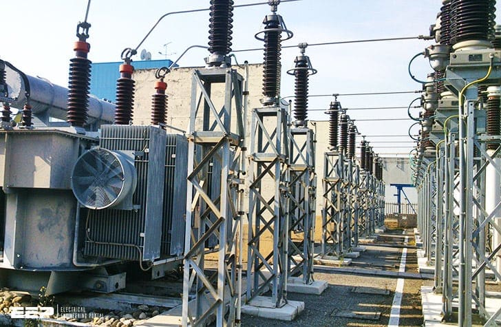
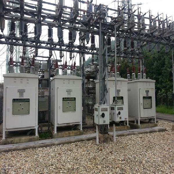
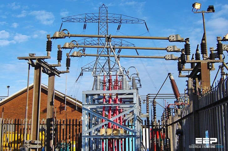
Distribution substation
Distribution substation is a substation from which electric supply is distributed to the different users. In a substation there are numbers of incoming and outgoing circuits each having its isolator, circuit breaker, transformers etc. connected to bus-bar system.
 Ten equipment you MUST recognize in every distribution substation
These equipment are mostly static type.
Safety and protection of equipment as well as working personnel is also a considerable factor. Lightening arresters, earthing of equipment and fencing is done for this purpose.
The following equipment are installed in distribution substations:
- Distribution Transformer
- Circuit breaker
- Lightning Arrester
- Air Break (AB) switches / Isolator
- Insulator
- Busbar
- Capacitor Bank
- Earthing
- Fencing
- Distribution panel board
1. Distribution Transformer
The distribution transformer is a main and largest equipment of distribution substation.
It is basically a static electrical device which steps down the primary voltage of 33kV or 11 kV to secondary distribution voltage of 415-440 volts between phases and 215 volts between phase and neutral through delta-star windings by electromagnetic induction without change in frequency.
A transformer is a four-terminal equipment that converts an AC input voltage into a higher or lower AC output voltage. It transmits power from one circuit to another without altering frequency, irrespective of voltage levels. The transformer comprises three principal components: the primary winding, functioning as the input; the secondary winding, serving as the output; and the iron core, which enhances the created magnetic field.
Transformers facilitate the transfer of electrical energy between fully insulated circuits, enabling the utilization of higher (stepped-up) voltages for transmission lines, which therefore provides a reduced (stepped-down) current. Increased voltage and lowered current diminish the necessary dimensions and expenses of transmission lines while also minimizing transmission losses.
They do not demand as much attention as most other devices; yet, the care and maintenance they necessitate is essential. Due to their reliability, maintenance is occasionally neglected, resulting in diminished service life and potential failure.
Transformer equipment
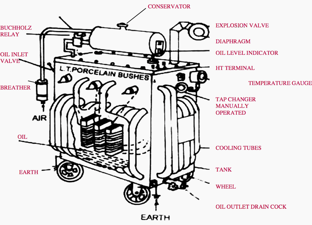
Transformer consists of the following parts and components.
- Primary winding
- Transformer tank
- Cooling tubes
- Buchholz Relay
- Tap changer
- Oil outlet valve
- L.T. terminals
- Temperature gauge
- Secondary winding
- Conservator
- Breather
- Explosion vent
- Oil inlet valve
- Oil level indicator
- H.T. terminals
Figure 1 – 3 Phase, 500 kVA, 11/0.433 kV Natural Air Oil Cooled Distribution Transformer
Important Transformer Equipment
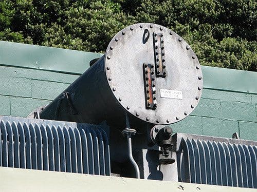
Conservator
(Equipped with transformer of rating 500 kVA and above)
It is a drum containing transformer oil and mounted at the top of the transformer and connected to the main tank by a pipe. As the volume of oil of transformer tank expands and contracts according to heat produced, this expansion and contraction of oil causes the level of the oil in conservator to rise and fall.
A small oil expansion vessel is supplied for the On-Load Tap Changer.
The magnetic oil level gauge is installed on the main conservator and can trigger an alarm or trip if the oil level drops below predetermined thresholds for whatever reason.
To summarize, the aim of conservator is to:
- Maintain the oil level in tank
- Provide space for the expanded oil
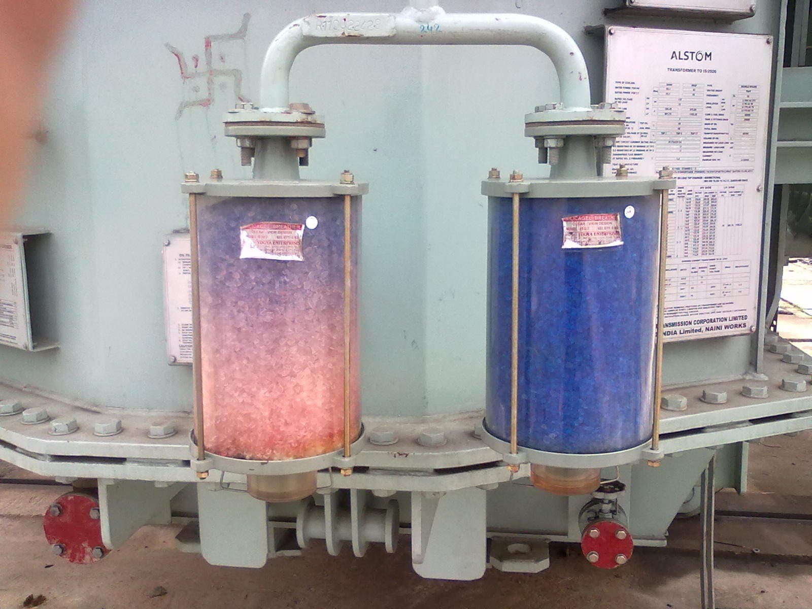
Breather
It is attached to conservator tank and contains silica gel, which prevents the moist air from entering into the tank during contraction of oil. When oil is hot there is expansion and gas passes to atmosphere through it. When oil is cooled, it contracts and the air enters in it.
The expansion and contraction of oil induce breathing activity. The silica gel desiccant breather absorbs moisture from the air that is breathed in. An oil seal in the air inlet limits the absorption of external moisture during periods of inactivity.
The silica gel crystals are usually bright orange when non-carcinogenic and transition to purple or bluish upon exposure to moisture.
The breather’s dimensions are selected to ensure effective operation for approximately six months. The selection of the appropriate size of silica gel breather for a certain transformer is influenced by several parameters, including the oil volume in the transformer, the adsorption capacity of the silica gel, the loading pattern, and the present air conditions at the site.
To summarize, silica gel breather prevents transformer oil from moisture contamination.
Buchholz Relay
It is protective relay of transformer. This device signals the fault as soon as it occurs and cuts the transformer out of the circuit immediately. This is gas operated protective relay. It is installed in between the pipe connecting the tank and the conservator.
It consists of two operating floats A and B. These are operated by two mercury switches separately provided for each float. The float A is for bell alarm and float B is for operating the tripping circuit.
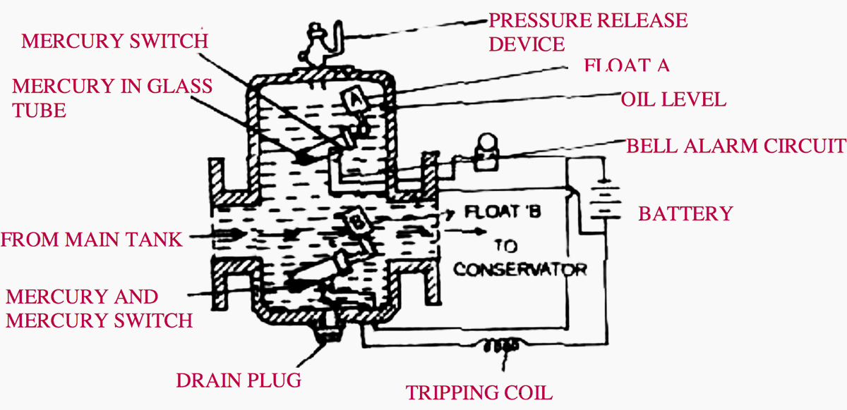
Whenever there is a minor fault or low level of oil, the bell alarm operated by float ‘A’ and whenever there is severe fault in the transformer, float ‘B’ operated due to excessive gases. It trips the circuit breaker and transformer is put out of circuit.
Power transformers are regarded as very reliable equipment; yet, protection devices are necessary to maintain the service continuity demanded by modern conditions.
In an optimal scenario, protective devices should be responsive to all faults, user-friendly, durable for operation, and cost-effective. In the context of liquid-immersed transformers, a nearly optimal ‘protective device’ is represented by the Gas and Oil relay discussed herein. This gas is accumulated in the relay’s body and is utilized to activate the alarm or tripping circuit.
The Gas and Oil relay principle was initially effectively proven and employed by ‘Buchholz’ many years ago.
Explosion Vent
A major fault inside the transformer causes instantaneous vaporization of oil, leading to extremely rapid buildup of gaseous pressure. If this pressure is not released with in few milliseconds, the transformer tank can rupture, spilling oil over a wide area.
An explosion vent provides instantaneous releasing of such dangerous pressure and protects the transformer.
Delaying the replacement of the outer diaphragm will let moisture intrusion, leading to oil contamination. If the diaphragm has been damaged due to a transformer malfunction, an inspection must be conducted to ascertain the nature and origin of the defect.
Oil level Indicator
An oil level indicator indicates level of transformer oil at the conservator of the transformer. It has markings on transparent sheet for maximum and minimum levels. An oil level gauge is necessary to ensure the proper maintenance of the oil level. A mark on the gauge often denotes the 25°C level, representing the appropriate oil level at that temperature.
A significantly low oil level can expose electrified and current-carrying components intended for operation in oil, potentially leading to overheating or electrical flashover. An excessive oil level may result in over pressurization due to oil expansion.

Watch Video – Oil level indicator
Inlet Valve
It provides passage to pour the transformer oil in the tank during purification or in case of shortage found in the tank.
Outlet Valve
It provides passage to drain the oil during overhauling or as and when required oil sample for testing.
Cooling Tubes
These tubes provide better and effective cooling of transformer oil by increasing the surface area of tank to the atmosphere.
Tap changer
The tap changer is used to regulate the output voltage manually according to line voltage. The taps of transformer can be changed by the tape changer manually. It is provided on HV side so that the voltage on LV side feeding to the load can be maintained.
Normally tap selection range is ± 15 % in steps of 2.5 %.
At low-current ratings, off-circuit switches are not affected by the issues associated with pyrolytic carbon that complicate high-current applications, hence resulting in a preference for tap changing via off-circuit links in significantly larger units.
2. Circuit Breaker
The circuit breaker is an equipment which automatically cut off power supply of the system when any fault or short circuit occurs in the system. It detect and isolate faults within a fraction of a second thereby minimizing the damage at the point where the fault has occurred.
The circuit breakers are specially designed to interrupt the very high fault currents, which may be ten or more times the normal operating currents.
High-voltage circuit breakers are critical components in power systems. They are engineered to function as interrupting devices in both standard operations and fault conditions. HV circuit-breakers are anticipated to function seamlessly in all applications. Furthermore, it goes without saying that they MUST be capable of operation at any moment, even following an extended duration of inactivity.
The primary functions of high-voltage circuit breakers can be classified into four categories:
- Switching-off operating currents
- Switching-on operating currents
- Short-circuit current interruption
- Secure open and closed position
The components of high-voltage circuit breakers, concerning fundamental functions, can be categorized into five groups:
2.1 Insulation
The electrical insulation of high-voltage circuit breakers is achieved by a combination of gaseous, liquid, and solid dielectric materials. The failure of insulation can cause significant damage, including flashover between phases, to ground, or across the open poles, necessitating extensive repair or replacement.
To avoid such failures, the insulation must be maintained and tested. The quantity of insulating medium must be consistently monitored; the quality of insulation requires frequent assessment by diagnostic procedures, and the insulation distance should be evaluated using position transducers and visual inspection.
2.2 Current Carrying
The current carrying components are essential elements that ensure the flow of current in a closed circuit. The malfunction of these components can result in catastrophic occurrences, including contact welding and significant degradation of the insulation system. It has been observed that the contact deterioration process requires several years to attain its final phases. In practice, the majority of contact issues may be mitigated with regular diagnostic testing.
The methodologies for current-carrying testing can be performed by the assessment of contact resistance, contact temperature, load current, and gas decomposition content.
2.3 Switching
High voltage circuit-breakers experience electrical, thermal, and mechanical stresses during operation. They must be capable of managing substantial power loads without inducing failures. The metrics utilized for monitoring and diagnosing switching include the position of primary contacts, contact travel characteristics, operating time, pole discrepancies in operating times, arcing duration, and arcing contact wear.
Contact travel characteristics are the predominant metrics employed in periodic testing to examine contact movement.
MV/HV switchgear (circuit breaker) switching capability and suitability for specific applications
2.4 Operating Mechanism
The operational mechanism is a component utilized to transition contacts between the open and closed positions, or vice versa. Failures of the operational mechanism constitute a significant percentage of total failures in high-voltage circuit breakers. For instance, the leaking of oil and gas in hydraulic and pneumatic systems is prevalent, however it may be managed without interrupting the system.
The failure of shafts, rods, and springs may cause significant malfunctions, resulting in system interruptions.
Dos and don’ts in operating LV/MV circuit breakers, relays, disconnectors and fuses
2.5 Control and Auxiliary Functions
Control and auxiliary components operate with 110-220 volts direct current. A signal goes to the coil to activate a latch or open a valve, resulting in the release of energy from a mechanical drive. The control and auxiliary components, consisting of electrical circuits and latches or valves, are prone to failures with considerable frequency.
Common malfunctions in these components include an inability to open or close on command, as well as operational delays. The parameters that must be monitored for control and auxiliary systems include coil current, voltages, the state of auxiliary switches, circuit continuity, and the environment of the control cabinet.
Circuit breaker schematics in a nutshell: Tripping, closing and blocking coil arrangements
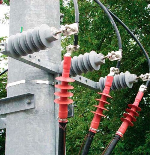
3. Lightning Arrester
Lightning arrester is a most important protective device of distribution substation to protect valuable equipment as well as working personnel. It arrests and discharges over voltage to earth during lightning strokes. These are installed between line and earth near equipment.
Representative values of a lightning stroke:
- Voltage: 2 × 10⁻⁸ volts
- Current: 2 × 10⁴ Amps
- Duration: 105 seconds
- Power: 8 × 10⁵ kW
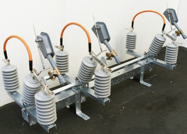
4. Air Break (AB) Switch / Isolator
Air break switches are used to isolate substation equipment for maintenance and also for transfer of load from one bus to another. Lay-out of substation depends upon type of Air break switches. These switches are of two types vertical break type or horizontal break type. Horizontal break type normally occupies more space than the vertical break type.
Disconnect switches are engineered to continuously conduct load currents and temporarily carry short-circuit currents for a defined duration, often measured in seconds or cycles based on the short-circuit current magnitude. They are engineered for no-load switching, facilitating the opening or closing of circuits where minimal currents are established or interrupted, including capacitive, resistive, or inductive currents, or when there is an insignificant voltage across the open terminals of the switch.
Vertical break switches are the predominant and most versatile design of disconnect switches, capable of installation with minimal phase spacing. Their rotating blade design makes them particularly suitable for cold/ice environments, while their contact design is ideal for high fault current locations.
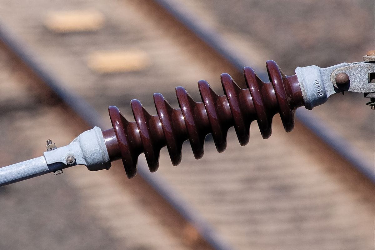
5. Insulator
The main function of an insulator is to insulate live conductor or substation equipment at different voltages with reference to the ground structures as well as provide mechanical support.
Provision of adequate insulation in a substation is of primary importance from the point of view of reliability of supply and safety of personnel.
6. Busbar Arrangement
The busbar is a conductor used to connect two and more substation equipment located side-by-side when the currents are very high. These are usually rectangular, sometimes tubular, bare copper bars supported on insulators. The outdoor busbars are either of the rigid type or of the strain type.
In the rigid type, pipes are used for making connections among the various substation equipment. The strain type busbars are an overhead system of wires strung between two supporting structures and supported strain type insulators. Since the busbars are rigid, the clearances remain constant.
7. Capacitor Bank
It is a series parallel combination of capacitors required to improve power factor of the system. They act as reactive power generators, and provide the needed reactive power to accomplish active power of circuit. This reduces the amount of reactive power, and thus total power (kVA) or the demand.
The bank should be provided as near as possible to load.
Capacitor banks in substations: Schemes, relay settings, and protective measures
8. Earthing
Provision of an effective, durable and a dependable earthing in a substation and switching stations is very important for the safety of operating personnel as well as electrical devices. The voltage levels do not rise above tolerable thresholds and that the earth connection is rugged to dissipate the fault to the earth.
Earthing has a very low resistance and connects the substation equipment to the general mass of the earth. Recommendations for earthing of various equipment in substation is described in this technical article.
High voltage earthing system analysis and design for power substations and lines
9. Fencing Arrangement
Fencing is provided at outdoor substation yard for restricting entry of unauthorized person and livestock. It must be earthed/ grounded separately. Height of fencing normally should not be less than 1.8 metres. Fencing should be painted once in a year by suitable paint.
10. Distribution Panelboard
Distribution panelboard consists of MCCBs, control equipment, meters and relays are housed in the control room. The panel frame shall be connected to the earth grid by an earthing conductor. A rubber mat of prescribed size and quality shall lay in front of panel.
References:
- Handbook on Maintenance of Electrical General Services Substation by GOVERNMENT OF INDIA
- EHV substation layouts for busbar systems up to 400 kV system voltage – G.N. Mathur and R.S. Chadha
- The basics of switching equipment in high voltage substations by David L. Harris and David Childress
Related electrical guides & articles


Edvard Csanyi
Hi, I'm an electrical engineer, programmer and founder of EEP - Electrical Engineering Portal. I worked twelve years at Schneider Electric in the position of technical support for low- and medium-voltage projects and the design of busbar trunking systems.I'm highly specialized in the design of LV/MV switchgear and low-voltage, high-power busbar trunking (<6300A) in substations, commercial buildings and industry facilities. I'm also a professional in AutoCAD programming.
Profile: Edvard Csanyi

Excellent explainetion I see it is!
This is an interesting and brilliant site of all engineering students.
This is a brilliant site for me as an Electrical Engineer employed by a Power Utility.
I am a an electrical student I found sense in this when I graduate am wishing to be working from distribution substation I just like that work place.
I need more learning about the transformer power
Contact me (Engr. Sunday) for all your power, transmission station and switch yard related Civil Engineering works, I’m a certified Engineer with over a decade experience. Email: [email protected]
The images in the exported PDF files are blurry.
I found the information very educative, I got the information I want. Thanks
Very informative as am now joining substation maintenance team this month.
i need more inform about 330kv substation
Material required of 33KV substation materials
plz contract 03322398775
I have seen a 2.5MVA power transformer recently which has no conservator and no Buchholz relay, but has certain sensors. What do you make of this and what is your take on such a design?
what are the things required to make a best 6.6 KV indoor substation.
This is a very informative and educational article on substations. Thanks for taking time to write it. Let’s not forget that none of the protection circuits will work without a battery. Sadly, it’s frequently ignored and more than one substation has burned to the ground because it was not being maintained. If you’d like a short article on the topic I’d be happy to contribute. Best regards.
Edvard,
Sorry to carp, but there are minor typos in the lightning values (section 3):
Voltage should be 10^8 volts (100MV) – if it were really 10^-8 V (ten nanovolts) lightning would hardly be a problem!
Duration should be 10^-5s (10 microseconds); we should be rather thankful it’s not 10^5 sec. (i.e. lasting all day)!
Power should therefore be (2×10^8) x (2×10^4) = 4×10^12W (or 4×10^9kW) – though this would certainly be an extreme case.
Thanks for the article; regards, David Renshaw
I am a boy of 28years old of age
I am Electrician I work under contrat in (UBTH) university of Benin teaching hospital. I work on line
I will look e to work with you sir.
But I am also a graduate, I have Bsc computer science.
But I electrical work Right from my technical School
Plz sir help me