
Estimated Study Time: 8 minutes
Design of the earth-termination system for equipotential bonding
The electrical low voltage consumer’s installation requiring certain earthing resistances (disconnection conditions of the protective elements) and the foundation earth electrode providing good earthing resistances at cost-effective installation, the foundation earth electrode is an optimal and effective complement of the equipotential bonding.
The design of a foundation earth electrode is governed in Germany by DIN 18014, which, for example requires terminal lugs for the earthing busbar. If a foundation earth electrode is used as lightning protection earth electrode, additional requirements may have to be considered.
Equipotential bonding conductors (in future: protective bonding conductors) Equipotential bonding conductors should, as long as they fulfil a protective function, be labelled the same as protective conductors, i.e. green/yellow.
The decisive factor for the design of the main equipotential bonding conductors in accordance with IEC 60364-5-54 and HD 60364-5-54 is the cross section of the main protective conductor. The main protective conductor is the one coming from the source of current or from the service entrance box or the main distribution board.
Table 1 – Cross sections for equipotential bonding conductors
| Main equipotential bonding | Supplementary equipotential bonding | ||
| Normal | 0.5 x cross section of the largest protective conductor of the installation | between two bodies | 1 x cross section of the smaller protective conductor |
| between a body and an extraneous conductive part | 0.5 x cross section of the protective conductor | ||
| Minimum | 6 mm2 | with mechanical protection | 2.5 mm2 Cu or equivalent conductivity |
| without mechanical protection | 4 mm2 Cu or equivalent conductivity | ||
| Possible limit | 25 mm2 Cu or equivalent conductivity | – | – |
In any case, the minimum cross section of the main equipotential bonding conductor is at least 6 mm2 Cu. 25 mm2 Cu has been defined as a possible maximum. The supplementary equipotential bonding (Table 1) must have a minimum cross section of 2.5 mm2 Cu for a protected installation, and 4 mm2 Cu for an unprotected installation.
For earth conductors of antennas (according to IEC 60728-11 (EN 60728-11)), the minimum cross section is 16mm2 Cu, 25 mm2 Al or 50 mm2 steel.
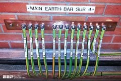
Equipotential bonding bars
Equipotential bonding bars are a central component of equipotential bonding which must clamp all the connecting conductors and cross sections occurring in practice to have high contact stability; it must be able to carry current safely and have sufficient corrosion resistance.
DIN VDE 0618-1: 1989-08 (German standard) contains details of the requirements on equipotential bonding bars for the main equipotential bonding.
- 1 x flat conductor 4 x 30 mm or round conductor Ø 10 mm
- 1 x 50 mm2
- 6 x 6 mm2 to 25 mm2
- 1 x 2.5 mm2 to 6 mm2
These requirements on an equipotential bonding bar are met by type K12 (Figure 1).
This standard also includes the requirements for the inspection of clamping units of cross sections above 16 mm2 with regard to the lightning current ampacity. Reference is made therein to the testing of the lightning protection units in accordance with EN 50164-1.
If the requirements in the previously mentioned standard are met, then this component can also be used for lightning equipotential bonding in accordance with IEC 62305-1 to 4 (EN 62305-1 to 4).
Terminals for equipotential bonding
Terminals for equipotential bonding must provide a good and permanent contact.


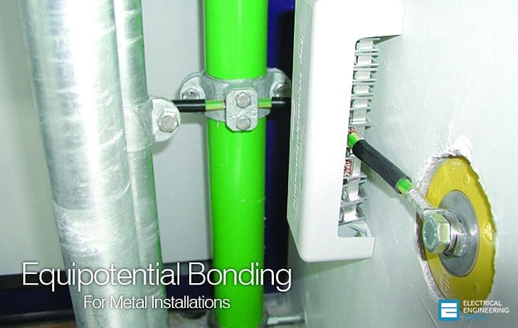
Integrating pipes into the equipotential bonding In order to integrate pipes into the equipotential bonding, earthing pipe clamps corresponding to the diameters of the pipes are used (Figure 2, left and middle picture).
Pipe earthing clamps made of stainless steel, which can be universally adapted to the diameter of the pipe, offer enormous advantages for mounting (Figure 2, right picture). These pipe earthing clamps can be used to clamp pipes that are made of different materials (e.g. steel, copper and stainless steel).
These components allow also a straight-through connection. Figure 3 shows equipotential bonding of heating pipes with straight-through connections.

Test and inspection of the equipotential bonding
Before commissioning the electrical consumer’s installation, the connections must be inspected to ensure their faultless condition and effectiveness.
A low-impedance conductance to the various parts of the installation and to the equipotential bonding is recommended. A guide value of < 1 Ω for the connections at equipotential bonding is considered to be sufficient.
Supplementary equipotential bonding
If the disconnection conditions of the respective system configuration can not be met for an installation or a part of it, a supplementary local equipotential bonding is required. The reason behind is to interconnect all simultaneously accessible parts as well as the stationary operating equipment and also extraneous conductive parts.
Moreover, the supplementary equipotential bonding must be used for installations or parts of installations of IT systems with insulation monitoring.
The supplementary equipotential bonding is also required if the environmental conditions in special installations or parts of installations mean a particular risk. The IEC 60364 series Part 7 draws attention to the supplementary equipotential bonding for operational facilities, rooms and installations of a particular type.
These are , for example:
- IEC 60364-7-701 Rooms with bathtub or shower
- IEC 60364-7-702 Swimming pools and other basins
- IEC 60364-7-705 For agricultural and horticultural premises
The difference to the main equipotential bonding is the fact that the cross sections of the conductors can be chosen to be smaller (Table 1), and also this supplementary equipotential bonding can be limited to a particular location.
Reference: Lightning Protection Guide – www.dehn.de
Related electrical guides & articles


Edvard Csanyi
Hi, I'm an electrical engineer, programmer and founder of EEP - Electrical Engineering Portal. I worked twelve years at Schneider Electric in the position of technical support for low- and medium-voltage projects and the design of busbar trunking systems.I'm highly specialized in the design of LV/MV switchgear and low-voltage, high-power busbar trunking (<6300A) in substations, commercial buildings and industry facilities. I'm also a professional in AutoCAD programming.
Profile: Edvard Csanyi

Is it necessity to have bonding of motor and pump having MS base frame?
In case of short circuit to the ground somewhere in the installation Tia current will flow to the earthing and the equipotential earthing.
That’s the reason of big copper connection
edvard , again you bring it home . thank you
The only oversight I noticed is the fact tjat there are torque spefication that are not mentioned. However, I find this very important due to if not met could be the loss of a proper bond to reference ground.
I have had this in the field and what occurs is ecentally what is called a dirty open. Corrosion builds between the different metal types if a proper torque is not met. Possible that the specific’s could be listed in the given codes. I thought I would give this a mention. Correct me if I’m wrong. Thank you great information.
here the usual maximum bonding upper limit is 35 sqmm Cu when installed partialy underground as it is equivalent to a grounding rod.
i was surprised when recently checking a 400KV new station grounding of American design to find bonding with 240 sqmm Cu wires. Does anyone knows the reason for such huge quantities of copper ?
abraham rothenberg
electrical engineer inspector