
Estimated Study Time: 26 minutes
Quality of erection and commissioning
Erection and commissioning of MV/HV switchgear are quite complex and full of tiny little details that can easily make your project slow down or even stop. Not to mention deadlines and penalties which are hanging over everybody’s heads involved in the project. This article is divided into two parts. This part deals with the inspection, installation, and assembly of MV/HV outdoor and indoor switchgear.
 Guide to erection and commissioning of MV/HV switchgears (Inspection, installation and assembly)
Often the switchgear cannot be shipped in completely assembled condition due to limitations of transportation and packing. The erection includes placing the equipment on its foundation, completion of assembly, i.e. assembly of items/sub-assemblies supplied loose, their mechanical and electrical inter-connection, fitting of any extra instruments/devices, and completion of control and power circuits.
Once the equipment is erected, it needs to be commissioned through generally pre-defined checks and tests before finally putting into service. Testing is necessary to prove that the installation meets the required specifications and safety. The work content for the installation of outdoor switchgear is different from that of indoor switchgear, but the principles followed are the same.
The availability of following documents should be ensured during erection and commissioning:
- Dispatch/delivery documents, i.e. Packing list;
- Instruction manual for operation and maintenance;
- Outline general arrangement, layout and floor plan drawing, Foundation drawing;
- Schematic and wiring diagrams; and
- Instruction manuals for relays, meters and other devices like switches, transducers, etc. fitted into the equipment.
- Dispatch
- Inspection On Receipt at Site
- Storage And Handling
- Installation
- Erection of switchgear
- Assembly of Switchgear
1. Dispatch
After manufacturing and completion of all routine tests and other quality and inspection checks, the switchgear is dismantled for packing and is made ready for dispatch. As many a time complete assembly cannot be dispatched due to transport limitations, these are made ready for dispatch after dismantling.
Following procedure and precaution should be followed while dispatching switchgear:
1.1 Outdoor Switchgear
Outdoor switchgear are generally designed and dispatched so as to involve minimum amount of erection work. It is generally dismantled into four parts as follows:
- Pole unit with inter-phase mechanism
- Mechanism box with local control unit
- Structure for circuit breaker, and
- CTs and VTs.
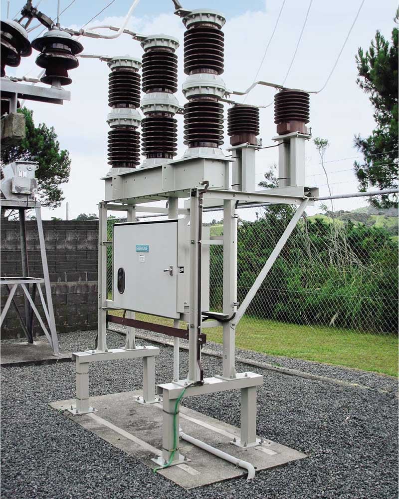
An assembled outdoor vacuum circuit breaker (VCB) is shown in Figure 1 below.
The interconnecting drive rod with eyebolts (Figure 8) is de-linked and kept tied inside the inter-phase mechanism. The connecting hoods are kept inside the mechanism house. Structure parts are dismantled and tied together. These parts are marked suitably to facilitate easy assembly at site.
Openings on the top of the mechanism housing and bottom of the inter-phase house are covered with blanking plates in order to avoid ingress of dust, rainwater and foreign bodies inside the units during transport and storage at site. These blanking plates are to be removed just before assembly.
Foundation bolts, loose hardware, terminal damps (if specified) and any other small items are packed in a small box which is fixed to the main packing box. The spring charging handle and slow closing handle are generally kept inside the mechanism house of each unit.
The structure assembly is packed separately with damps for easy transportation. The pole unit with inter-phase assembly is packed in a wooden crate, while the mechanism house is packed in a separate wooden box. In case of a breaker with outdoor CTs/VTs and associated mounting structure, the three single-phase CT/VT are packed in a separate packing case.
Suitable pictorial marks are made on the packages to ensure that the handling and transport are done in an upright position. While lifting by a crane or hoist, wire ropes should be attached to the bottom of the crate.
1.2 Indoor Switchgear
Indoor metal-clad switchgear up to 33 kV class should be dispatched by the following rules:
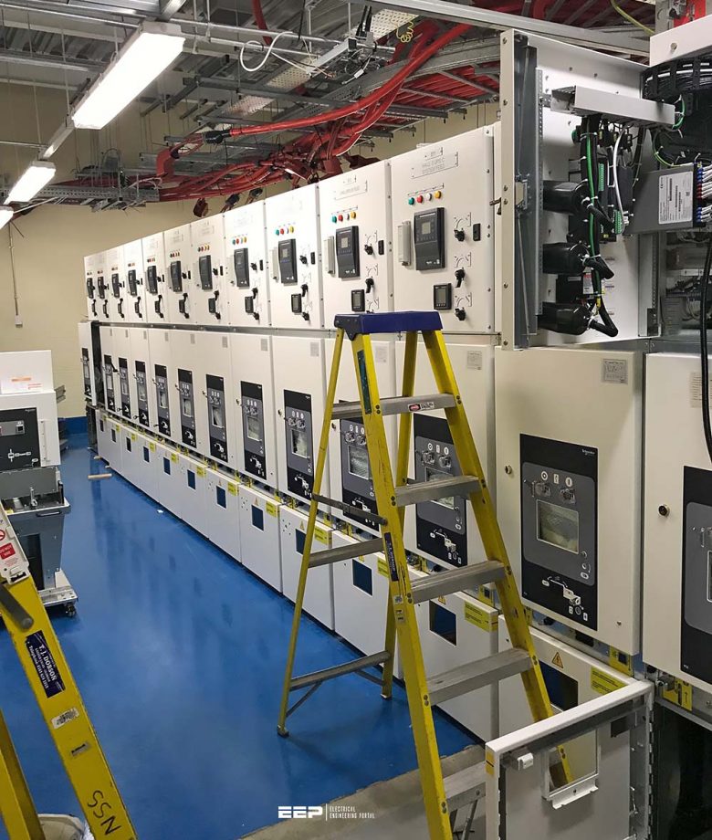
Rule #1 – For easy transport and handling, the switchboard is divided into dispatchable units, and generally two or three (Figure 2) panels are sent as one dispatchable unit depending upon the dimension of the panel, considering transport and shipping limitations.
Rule #2 – As far as possible, the bus-coupler panel with trunking panel and incomer panel with separate feeder VT panels are sent as one unit respectively so that minimum connections are required to be done at site.
Rule #3 – Panels are fully covered by polythene sheets to protect them from dust and moisture, and are packed in a wooden crate. Suitable felts are provided to protect the painted surface when it comes into contact with crates.
Rule #4 – Before packing, the withdrawable VCB truck is kept in service position inside the panel and the circuit breaker contacts are kept in open condition. The closing spring of the operating mechanism is kept in ‘free’ (discharged) condition.
Rule #5 – Suitable pictorial marks are made on the packages to ensure that the handling and transport are done in an upright position. When lifting by a crane or hoist, wire ropes should be attached to the bottom of the crate.
Rule #6 – For each consignment, a dispatch advice note and packing list are sent so that the units and corresponding accessories can be unpacked and identified. Each crate is marked with the Serial No. of the units kept within it.

2. Inspection On Receipt at Site
Switchgear is often dismantled before being dispatched with the parts packed separately. All items of equipment should therefore be carefully inspected as soon as possible upon arrival at site to ascertain whether any items are missing or damaged. Hence, after unpacking, the contents should be checked against dispatch notes and the receipt of all items verified.
The recipient should check for damages, if any, which might have occurred during transport or handling.
In particular, he should carefully check for damages in the vacuum interrupter, inter-phase barriers, bushings, relay and epoxy insulators. If any damages are noticed, communication of the same may be sent to the transportation company, insurance company and a copy to the manufacturer.
Related electrical guides & articles


Edvard Csanyi
Hi, I'm an electrical engineer, programmer and founder of EEP - Electrical Engineering Portal. I worked twelve years at Schneider Electric in the position of technical support for low- and medium-voltage projects and the design of busbar trunking systems.I'm highly specialized in the design of LV/MV switchgear and low-voltage, high-power busbar trunking (<6300A) in substations, commercial buildings and industry facilities. I'm also a professional in AutoCAD programming.
Profile: Edvard Csanyi
