
Earthing of low voltage networks
The earthing of low voltage networks in the UK is largely determined by the Low Voltage Supplies. However, if the incoming supplies are at 11kV and the transformers are in the ownership of the user, the LV supplies may be earthed in a less conventional way using a high impedance. This arrangement is not allowed for public supplies.
However, it is a useful system when it is more important to maintain supplies than it is to clear the first earth fault.
EXAMPLE: An emergency lighting scheme for the evacuation of personnel from a hazardous area could use a high impedance system if it were considered less dangerous to maintain supplies after a first earth fault than to disconnect the light completely. The Channel Tunnel could be such a case.
Even in these circumstances the original earth fault should be corrected as quickly as possible.
The more conventional earthing arrangements are:
- TN-C where the earth and neutral are combined (PEN) and
- TN-S where they are separated (5 wire) or
- TN-C- S.
The latter is very common as it allows the single-phase loads to be supplied by phase and neutral with a completely separate earth system connecting together all the exposed conductive parts before connecting them to the PEN conductor via a main earthing terminal which is also connected to the neutral terminal.
For conductors which are not of the same material the cross-sectional area shall be adjusted in the ratios of the factor k from Table 43A in BS 7671. The k factor takes into account the resistivity, temperature coefficient and heat capacity of the conductor materials and of the initial and final temperatures.
Lastly there is the TT system which uses mother earth as part of the earth return.
The neutral and the earthed parts are only connected together via an electrode system back to the source earth (and neutral). To check that conventional systems are satisfactory, i.e. that the protection operates on the occurrence of an earth fault, it is necessary to calculate the earth fault loop impedance (Zs) and ensure that the fault current through it will cause the protection to operate.
This is quite a tedious process, involving as it does the calculation of the impedances afforded not only by the earth return but also by:
- The phase conductor
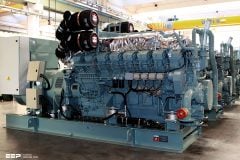
- Supply transformer
- Supply network
- Any neutral impedance.
This information must be requested early. The Electricity Distributor should be able to give the fault level or the equivalent impedance of the supply network and the manufacturer can provide the appropriate impedances for the transformer.
However, time will be required to obtain the answers so enquiries should be made at the commencement of the project.
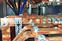
The substation will house the circuit breakers of fuses for the main cable connections to the sub-distribution boards and motor control centres. These protective devices must discriminate with those further down the line nearer the ultimate loads. A system study must therefore establish the correct ratings of the substation equipment to discriminate with the distribution network.
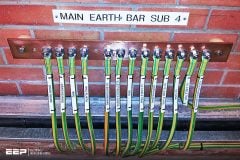
Earthing of equipment should be electrically complete and confirmed mechanically sound and tight.
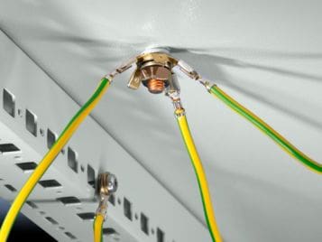
Earthing conductors (previously termed earth leads) must be checked for compliance with the IEE Regulations, i.e. they must not be aluminium and they must be not less than 25 mm2 for copper and 50 mm2 for steel, unless they are protected against corrosion. These conductors are for connection to the earth electrodes.
Another important point to bring out is that the earthing conductor to the earth electrode must be clearly and permanently labelled ‘SAFETY ELECTRICAL CONNECTION – DO NOT REMOVE’ and this should be placed at the connection of conductor to the electrode.

Fuse ratings should also be checked in relation to other fuse ratings in the supply circuit or against the settings of protective relays to assure correct sequence of operation and discrimination. Circuit charts for distribution boards should be completed and designation labels fitted to ensure safe operation of switches and isolators.
All tests should be carried out as required in BS 7671, Part 7, and an Electrical Installation Certificate given by the contractor to the person ordering the work.
Many installations now incorporate rcds and fault current operated protective devices. These also must be tested using appropriate test equipment, full details of which can be found in BS 7671 or for more elaborate apparatus in BS 7430 and Guidance Notes which are published separately and amplify the requirements in the British Standard.
The nominal voltages at present are:
- 230V + 10% and -6%
- 400V + 10% and -6%
Reference: Handbook of electrical installation practice fourth edition – Eur Ing GEOFFREY STOKES


sir a server room supply 3phase 4wire and the current running as R-16A,Y-20A,B-18A and N-18A(is very high to the Phase load) What do I do in this situation?
“When the phase conductor is above 16 mm2 then the protective conductor may remain at 16 mm2 until the phase conductor is 35 mm2, after which the protective conductor should be half the size of the phase conductor.”
I Have found this in BS7671 but can’t fathom if in a 3-phase system a PEN conductor should be S/2 (half the size) of a single line conductor or half of the sum of CSA of all 3 phases.
Can you help with this?
S / 2 (половината от размера) на еднолинен проводник
When we use TN-S System in India… In that case we doesn’t carry earth conductor from Dist. S/S /Source to Our Home. Also we take separate Earthings near home for return path. Means no actual connection between home earthing & Source side earthing… It means we use TT Type earthing?
Contact No – +91 9561573214
application not mentioned. please.
in system LN-C did i connect RCD?
Hi Ed,
I am an electrical engineer in the US. I am putting together a 2 hour presentation about Grounding & Bonding to our association. I wanted to compare US and Europe Grounding/Eating systems. I enjoyed this article. It is very helpful.
Thank you
Hi,
TNC system let us to consider PE & N together. Now, I want to know that, whether seeing PEN system from transformer to distribution panel then PEN system from distribution panel to Building Lighting panel then PE & N separately from building lighting panel to consumer is right or not?
is the graph in above paragraph wrong one for TT system, there is no earthing in end side.
3pole (or) 4 pole MCCB used in TNC earthing system.
Hi Thet,
3Pole MCCB shall be used in TNC earthing system as PE is not allowed to be switched for safety issue. Hence, this earthing system is not suitable for hazardous environment when neutral is required to be isolated.
Hope it makes sense
what is NET earthing
For TNS & TNCS system
What should be the Main Incomer cable Zero sequence impedance
hi
can i come and get full practical during holidays?
sir, i what to know the full name for the flowing TN-C, TT , TNC ,TNS
THANKS
T – Terra (ground)
N – Neutral
C – Combined
S – Seperate
TN-C = Terra Neutral – Combined
Earth and Neutral share the same conductor (2 wire single phase)
TN-S = Tera Neutral – Seperate
Earth and Neutral have seperate conductors (3 wire single phase L,N,E)
TNCS = Tera Neutral Combined Seperate
Starts out with combined neutral and earth, then they are seperated, ie from Minisubstation to Meterpanel combined earth and neutral (2-wire single phase) then then after meter panel to house DB neutral and earth become seperate wires (3-wire single phase)
TT = Tera Tera
Earth at source and Earth a Destination (no earth conductor between source and consumer, the soil is used as the earth return path.
Please could you amend your drawing of the TT supply as it is incorrect and should show the equipment being connected to the general mass of earth via an earth rod.
Exactly what i was thinking and thanks for requesting for the drawing to be ammended! :)
Sir,
Can we use one common earthing pit/rod for 3 or more buildings which have computer servers , medical equipment and say some other electronic load. the three building may be fed from one distribution transformer or different distribution transformers. Three phase 5 wire system BASICALLY TO REDUCE THE NUMBER OF EARTHING PITS.
In a TN-S earthing system can the neutral conductor disconnected simultaneously with the 3 phases ?
I want a clarification in one of our M/C it has 24V DC control ckt and only one motor with different gears to get differnent work at a time but not has any Variable Frequency Drive, i suggested to fix at Motor protection relay to vary the frequency however they connected at main supply and started varying it i know it is wrong but they asking how it is wrong? please clarify.
Thanks for the info. I want a clarification in one of our M/C it has 24V DC control ckt and only one motor with different gears to get differnent work at a time but not has any Variable Frequency Drive, i suggested to fix at Motor protection relay to vary the frequency however they connected at main supply and started varying it i know it is wrong but they asking how it is wrong? please clarify.
Very useful article.
ur posts are of great benefit to me, thanks. can u help me with pdf of electrical installation proceedual and iie regulations on protections
Thank you Ibrahim! Regarding el. installation document, I’m not quite sure what you’re looking for. Have you tried search box at the top-right?
Hello,
Thanks for the great efforts on EEP! It has been always useful for me to use your website during my work. I would like to know if there is any article regarding the touch and step voltage testing procedure for power plants and substations? because I tried to explore EEP many times but couldn’t find a specific steps to apply the measurements practically. your help is really appreciated.
important to maintain supply
What is type of earthing system used in India
It is TN-S in India vide IS 3043
please send me leaflets concerning about electrical engineering programes
Re hello,
In the representation of the TT system must put the metallic mass of the receiver to the ground.
And the IT system requires that the PE is the same for all receivers if the PE is not common to all receivers must be set to medium sensitivity differential protection on each departure.
Two PE conductors are separate from a distance of 8m.
In the IT system it is because common to all receivers PE a short-circuit may establish and solicited devices magnetic protection.
Kind regards
Pierre
Hello,
In the wiring diagram TNC (230V-400V ~) show two drivers who leave PEN.
It would be better to make a bridge over the mass of the receiver to show that the protective conductor has priority over the neutral conductor.
For sections of the PEN:
10 mm ² copper
Aluminum 16 mm ²
For sections of lower electrical conductors must change TNS.
This is the risk of mechanical failure of the electrical conductor.
You can spend TNC TNS but not vice versa.
Kind regards
Pierre
Is there a facility to make pdf and download the technical articles is there on android app.