
Estimated Study Time: 13 minutes
Proper specification of CTs
Current transformers (CTs) form an essential link within the protection chain of electrical networks. Their specification, even if it is handled by specialists, often includes errors and is insufficiently optimized. This often leads to technological impossibilities, operating delays, extra costs, incorrect operation of protections and can even jeopardize the safety of installations and people.
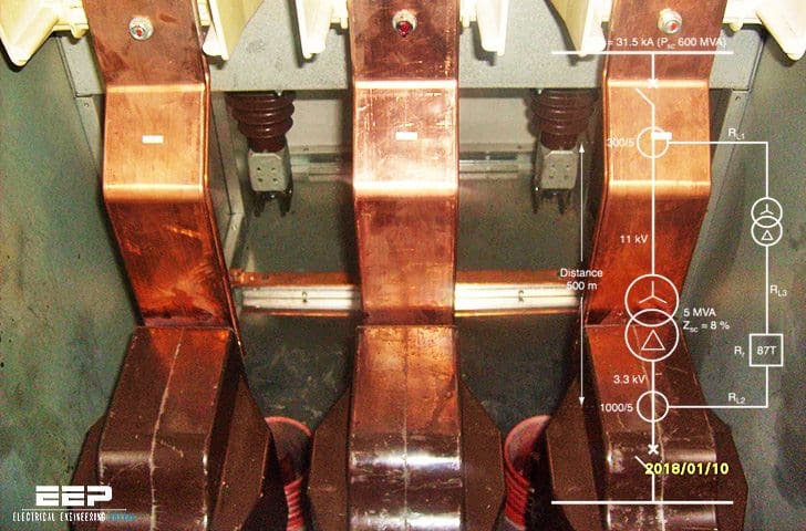 The most frequent errors in specifying current transformers (on photo: CTs installed in MV switchgear type MCset 1250A, 10kV, 31kA; credit: Edvard Csanyi)
Proper specification of CTs requires sound knowledge of:
- Electrical installation diagram,
- Electrical data (voltage, nominal current, short-circuit current, etc.),
- Associated protections,
- Overall network protections (protection plan, the load that they represent for the CTs, as well as wiring and their settings.
Common engineers errors
Many errors normally lead to oversizing of the CTs which increases costs and can be dangerous. Many CT definition errors stem from ignorance of their operation and from the unknown or incomplete characteristics of the network component to be protected and of the associated protections.
The better informed the CT manufacturer, the fewer errors and the more the CT will be optimised.
Contents
- Protections and conventional CTs
- Differential protections and class X
Protections and conventional CTs
For these protections which do not require class X defined CTs, the most frequent “errors” are:
Error #1 – Different accuracy limit factor or classes…
Using two CTs or one CT with two secondaries for two protective relays the manufacturers of which recommend different accuracy limit factor (ALF) or different accuracy classes.
As the CT manufacturers can translate 10P to 5P (according to the corresponding induction levels), and can move from one ALF to another by adjusting power, they can find a CT matching the needs of both relays.
Error #2 – Adding up the powers…
Taking into account the wiring resistance although the protection manufacturer has already integrated it into the needs formulated for the CT. Let us take an example of two relays whose technical data indicate for 1 A CTs:
- CT1 for relay 1: 5 VA 10P15 (assuming 2 RL < 1.5 Ω),
- CT2 for relay 2: 10 VA 5P15 (assuming 2 RL < 2 Ω).
A single CT may be suitable for both relays: in theory a 10 VA 5P15. You need to:
- Avoid adding up the powers (5 + 10 VA) required for each relay. In point of fact, for the CT2, relay 1 only represents a load (just like wiring) and vice versa.
- Check, in this case for the CT2, that: 2 RL + Rp1 ≤ 2 Ω;
and if CT1 was selected, that: 2 RL + Rp2 ≤ 1.5 Ω. If this was not verified, the relay supplier can suggest that “x” VA be added per additional ohm.
Error #3 – Changing the required characteristics…
Changing the required characteristics without verifying the consequences.
Case 1 – Low ratio CT…
A CT manufacturer cannot make a low ratio CT and suggests increasing this ratio. Let us take an example:
- Requested: 30/1 CT – 2.5 VA 5P20,
- CT manufacturer’s proposal: 60/1,
- With motor In = 16 A and minimum thermal protection setting: 40 % of CT In (i.e. 60 × 0.4 = 24 A).
The protection setting at 16 A (normal thermal protection setting at motor In), is then impossible. The solution is to increase the rating and lower the ALF requirement: 40/1 – 2.5 VA 5P10. This CT, feasible, allows the required setting (40 x 0.4 = 16 A).
Case 2 – Thermal withstand…
A buyer accepts a thermal withstand of 0.1 s proposed by the CT manufacturer instead of 1 s.
What is likely to happen is that, on a short-circuit, if the real fault duration exceeds 0.1 s, thermal and probably electrodynamic withstand will be insufficient and may result in CT destruction.
Error #4 – Lack of real information
Due to lack of information on real requirements. Let us take the following case, relatively educational: a CT with two primaries and three secondaries (200-1000/1-1-1) is requested with:
- First secondary: 1 A, class X (given ),
- Second secondary: 1 A 15 VA class 0.5 for metering,
- Third secondary: 1 A 10 VA 5P20.
Moreover, the supplier must comply with class X for both ratios! In point of fact, class X concerns only the 1000/1 ratio (for busbar differential protection). The 200/1 ratios concern metering and the traditional protections (see fig. 1).
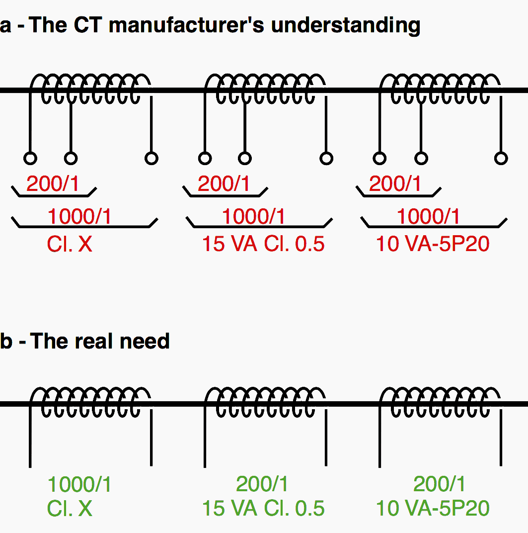
The CT to be manufactured is then easier, less bulky, cheaper and definitely feasible. This example shows that the lack of information shared between those involved is a source of errors and of non-optimization.
A consultation that does not begin properly may result in a CT that cannot be manufactured!
Error #5 – Taking into account relay impedance…
Taking into account the relay impedance Rh for calculation of real load (see fig. 2) in the CT calculation for overcurrent or in the calculation for CTs in class X.
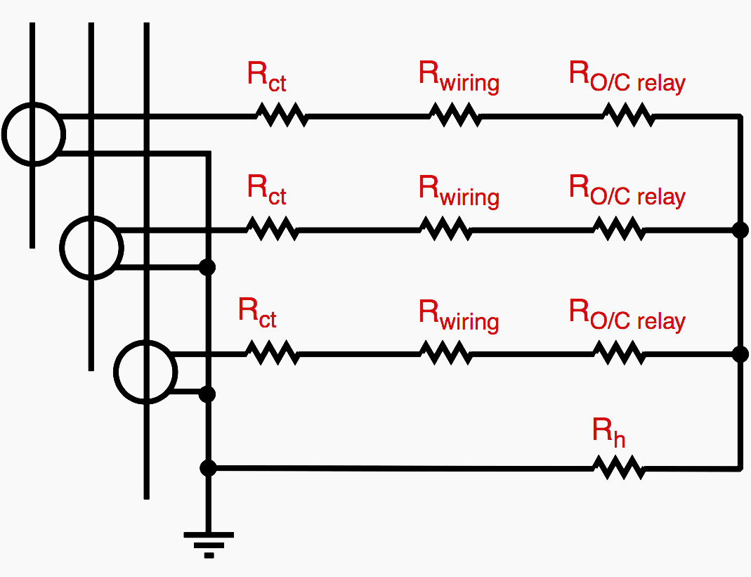
A word of warning! Rh is only considered when calculating CTs for zero sequence current lh.
For high impedance differential protections, in the calculation of Knee Point Voltage Vk given by:
2 If (Rct +2 RL + Ra)
where Ra = other loads, Rh must not intervene.
This is the load of one phase (we assume that no current flows through the neutral). Vk is indeed calculated for relay stability conditions, i.e. no phase or earth fault, in the protected zone, no incorrect unbalance, therefore, in the differential connection I = 0 and the voltage of that connection = 0.
Differential protections and class X
For these applications, the most usual errors are:
Error #1 – CTs with the greatest knee point voltage…
Asking the CT manufacturer to supply CTs with the greatest knee point voltage Vk that he can build using a standard mould. This occurs when the differential protection relay (make, type) is not defined.
There are three consequences:
- Overcost,
- Possibility of high overvoltages and overcurrents at the CT secondary which can lead to destruction of the circuit and the relay,
- With no requirements for the CT secondary winding resistance Rct, it is not certain that the Vk expression corresponding to the relay used, will be complied with.
For the relay used, the expression to be satisfied is: Vk ≥ 200 Rct + 20, i.e. 520 V. The Vk = 400 V is not sufficient!
More serious still, the requirement of too high a Vk may lead to the manufacturing of a non-standard CT (see the first two consequences above) requiring a specially designed stabilising resistance and an overvoltage limitor as well as the use of a deeper panel!
Error #2 – Error on the through current…
Error on the through current is very common. Let us take the example of a high impedance differential protection where the switchboard Isc is taken into account instead of the maximum through current. The aim is to protect a motor, the CTs have a ratio of 100/1.
- Result obtained with the through current (7 In of CT):
Vk ≥ 14 (Rct + 2 RL). - Result obtained with switchboard Isc (Isc = 40 kA):
Vk ≥ 800 (Rct + 2 RL)
The table 1 gives the through current values to be taken into account when the through current is the CT calculation base.

Error #3 – Pilot wires in the calculation…
With line differential protections, taking into account the pilot wires in the calculation of Rwiring. In point of fact, RL is given by the wiring linking the CTs to the relay located on the same side (end) of the line (see fig. 3).
You must not take into account the length of the pilot wires which run from one end to the other of the protected line.

Reminders
With respect to high impedance differential protections:
- For the calculation of min. Vk, take account of the through current (see Table 1).
- Calculation of the stabilising resistance Rst is a function of min. Vk and of the relay setting current.
- Calculation of peak voltage (Vp) is based on the internal Isc of the protected zone and on the real Vk of the CT.
Reference // Current transformers: Specification errors and solutions by P. Fonti (Schneider Electric)
Related electrical guides & articles


Edvard Csanyi
Hi, I'm an electrical engineer, programmer and founder of EEP - Electrical Engineering Portal. I worked twelve years at Schneider Electric in the position of technical support for low- and medium-voltage projects and the design of busbar trunking systems.I'm highly specialized in the design of LV/MV switchgear and low-voltage, high-power busbar trunking (<6300A) in substations, commercial buildings and industry facilities. I'm also a professional in AutoCAD programming.
Profile: Edvard Csanyi

what is the minimum time power interrupt of 2 of 3 MV switchgear
thanks
VERY GOOD AND IMPORTANT INFORMATION AND KNOWLEDGE IS PROVIDED IN THE FIELD OF POWER SYSTEM IN ELECTRICAL ENGINEERING . THANKS
It is a long confusion for me, when sizing the relay CT for Medium voltage switchgear outgoing feeders. Normally we do CT calculation to size the CT, but what the fault current value to be applied in the calculation. For example, a 13.8kV switchgear with 49kA rms symm current is feeding a transformer of 500kVA with voltage level- 13.8kV/480V with 5.75% impedance. The relay CTs are intended to give the protection functions such as 50/51. The transformer feeder primary is feeding from the said 13.8 kV switchgear outgoing feeders via cables of 185sq. mm of length 300meter. The ETAP calculation provided by the primary engineering consultant company showing 37.401kA fault current when fault point is between the transformer primary and outside the switchgear outgoing terminal , i.e at the cable running to the transformer.
So the point is, what’s the value of fault current to be considered in CT calculation. Whether it is 49kA ( rms symm value of 13.8kV switchgear) or 37.401kA ( the fault current at pony outside the Switchgear and before the transformer terminal).
Pdf please
Very informative. Thank You
VERY GOOD AND IMPORTANT INFORMATION AND KNOWLEDGE IS PROVIDED IN THE FIELD OF POWER SYSTEM IN ELECTRICAL ENGINEERING . THANKS
It would be great if you write how specify the CTs installed in neutral of transformer and how to size this neutral cable.
Hi I am reading this now.
Do you have any posts or information re calculating CTs requirements for neutral CTS installed in neutral of say 20MVA transformer
Thank you very much Eodvard , I study Electrical power system . I am very intersting and connect always your webset it is very helpful for me , so i want to friend with you because you are expert in my field .
best regards