
Estimated Study Time: 9 minutes
Low voltage switchboard construction
This technical article has the aim of helping the panel builder and the designer in the construction of ABB SACE ArTu low voltage switchboard. To this purpose, starting from the single-line diagram of a plant, it is possible to arrive – by selecting the suitable components – to the construction of an switchboard and to the relevant declaration of conformity with the Std. IEC 61439-2.
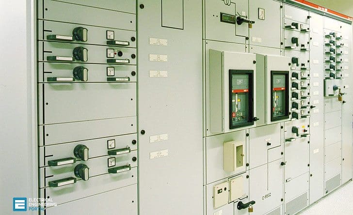 Example On How To Design a Low Voltage Switchboard (on photo: LV switchboard type 'MNS')
Characteristics of the low voltage switchboard, according to the specification:
- “not separated” switchboard;
- IP 65;
- exposed wall-mounted.
Single-line diagram
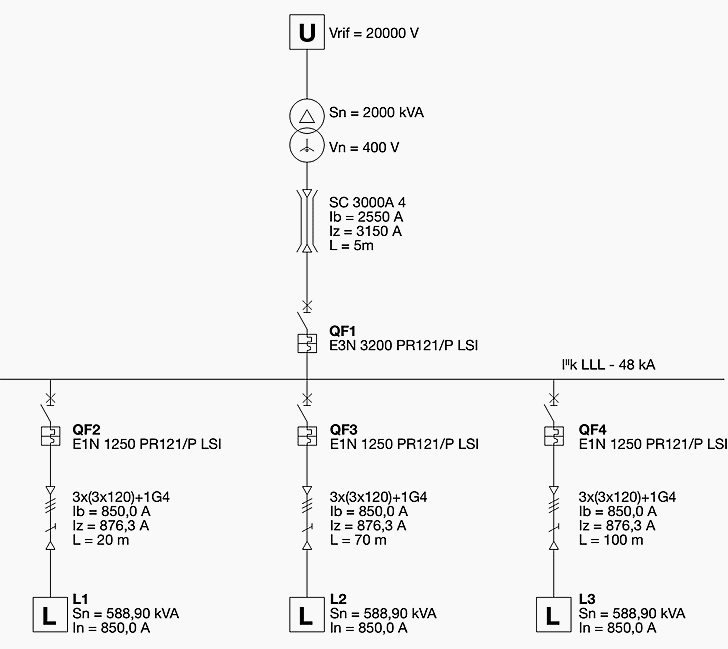
Let us suppose that realization of a main distribution switchboard is required, to be placed immediately on the load side of a 2000kVA MV/LV transformer. Three 850A outgoing feeders from this switchboard supply other distribution switchboard, but they are not dealt with.
Due to reasons of selectivity with other circuit breakers of switchboards on the load side, air circuit breakers have been chosen branched from the busbars. The main distribution busbar short-circuit current is 48 kA.
Selection of the circuit breakers and of the conductors external to the switchboard
Circuit breakers //
As shown in the single-line diagram, the circuit breakers chosen are:
- 1 pc. of Emax E3N3200 PR121/P-LSI In 3200 (main circuit breaker of the switchboard QF1);
- 3 pcs. of Emax E1N1250 PR121/P-LSI In 1250 (circuit breakers for the three outgoing feeders QF2, QF3, QF4).
Conductors:
- Incoming, from the transformer:
– 1 bus duct with Iz = 3150 A; L = 5 m - Outgoing from the switchboard, hypothesizing overhead installation on perforated trays, there are three low voltage cables:
– 1 cable L = 20m 3 x (3 x 120) Iz = 876,3 A;
– 1 cable L = 70m 3 x (3 x 120) Iz = 876,3 A;
– 1 cable L = 100m 3 x (3 x 120) Iz = 876,3 A.
Switchboard front, distribution system and metalwork structure
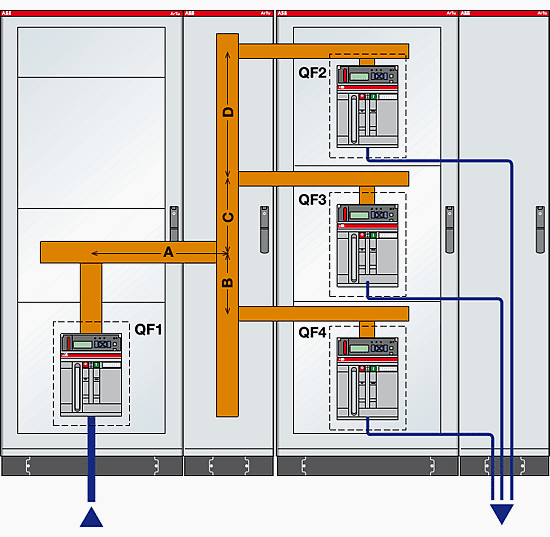
With regard to the positioning of the equipment, it has been decided to locate the main circuit breaker in one column, and the three outgoing feeders in another one. Since the power supply comes from below, it has been decided to position the circuit breaker QF1 at the bottom.
The switchboard assembly is of “not-separated” type. A possible layout of the busbars and of the circuit breakers is shown in the following figure:
Distribution system:
As regards the busbars inside the switchboard, by first approximation, they are selected according to the size of the circuit breaker:
Main distribution busbar system
Circuit breaker QF1
(From the “Distribution Switchgear – General catalogue”)
BA2000 In=3200 A (IP65); Icw max =100 kA
To get an Icw value suitable to the short-circuit current of the plant:
– 5 busbar holders PB3201 at a maximum distance of 425mm (Icw=50 kA) must be positioned.

Branch busbars of the circuit breakers
Circuit breakers QF2, QF3, QF4
(From the “Distribution Switchgear – General catalogue”)
BA1250 In= 1250 A (IP65) Icw max = 75 kA

To get an Icw value suitable to the short-circuit current of the plant:
– 5 busbar holders PB1601 at a maximum distance of 425mm (Icw=50 kA) must be positioned.
Joining pieces between circuit breakers and busbars
(circuit breakers QF2, QF3, QF4)
Table 11.2 of clause 11.4 of the Technical Application Paper shows the cross-sectional areas of the busbars for the connection of the circuit breakers:
- E3N323200 – A cross-sectional area 3 x (100 x 10)
- E1N121250 – A cross-sectional area 1 x (80 x 10)
Moreover, according to the terminal types, the maximum anchoring distance of the first anchor plate, shown at clause11.3 of the Technical Application Paper, shall be respected.

Joints for busbars //
As indicated in the “Distribution switchgear. General catalogue” the following joints are necessary:
- Joint from 3200 busbar to 3200 busbar, T joint, AD1073
- Joint from 3200 busbar to 1250 busbar, AD1078
Earthing busbar //
As shown on page 44 and 45 of this technical Application Paper, the earthing busbar shall have a minimum cross-sectional area equal to 1⁄4 of the cross-section of the main busbars. Therefore a bar 50×10 has been chosen.

Metalwork structure
As regards the metalwork structure, an ArTu K series switchboard with door (IP 65) is used. In order to house the circuit breakers, the vertical busbar system and the outgoing cables the following is used:
- 2 columns for the circuit breakers;
- 2 cable containers, one for the busbar system and one for the outgoing cables.
For a correct selection of the structure it is advisable to consult the “Distribution switchgear. General catalogue” where:
- to house Emax E1-E2-E3 circuit breakers a switchboard assembly with 800mm depth and 600mm width and one installation kit KE3215 are required.

The cable container has obviously 800mm depth and 300mm width. In the general catalogue for distribution switchgear the fixing crosspieces for busbars with shaped section can be found:
- For the 3200 A horizontal busbars (BA2000) the selected type of installation is number 5, for which the correct choice is two components TV6221 and one TV8011;
- For the 3200 A vertical busbars (BA2000) the selected type of installation is number 2, for which the correct choice is TV8101 component;
- For the 1250 A horizontal busbars (BA1250) the selected type of installation is number 5, for which the correct choice is two components TV6221 and one TV8011.

As specified in the general catalogue for distribution switchgear, the metalwork structure shall be completed by the side-by-side kits (AD1014).

References //
- Guidelines to the construction of a low-voltage assembly complying with the Standards IEC 61439 Part 1 and Part 2 – ABB
- Distribution switchgear General catalogue // ArTu K – ABB
Related electrical guides & articles


Edvard Csanyi
Hi, I'm an electrical engineer, programmer and founder of EEP - Electrical Engineering Portal. I worked twelve years at Schneider Electric in the position of technical support for low- and medium-voltage projects and the design of busbar trunking systems.I'm highly specialized in the design of LV/MV switchgear and low-voltage, high-power busbar trunking (<6300A) in substations, commercial buildings and industry facilities. I'm also a professional in AutoCAD programming.
Profile: Edvard Csanyi

Do you have LV switchboard design upto In =5000A ?
I am upgrading all schools power distribution boards to IP56 rating which should include ATS,Utility and genset power main switches, main KWHM metering 18 pole chassis to accommodate 250A, 100A, 400A MCCB for load and also inbuilt community board with a Check meter. Panel on plinth and weather proof. Board rating at 630A 3phase.
Can you assist me with advise and quotation to source from your company.
Cheers. Bradley Henao Licensed electrician. International Education Agency Papua New Guinea. Ph: 675 72762875 Cheers,
It’s very helpful for design various electrical power project
Best diagram developed with all systematic safety components can be operated balance load as per requirements in each phase through control panel.
thanks, good information.
AoA,
Respected Edvard,your are serving the humanity in general and engineering community in particular. May you live long for the sake of education.
With Best Regards :Engr. Muhammad Abdullah Khalid Seyal MSEE,MIEEE
Tanks
Mr Edvard,
Your presentation is worthy and very educative. Thanks a lot.
Very educative. You groom me. Can I get soft copies of these articles on my email please.
Excellent Presentation. Some of the contribution by readers are quite interesting. Where we can find the answer / replies to those questions,
Very educative. Thanks so much.
Thanks Mr. Edvard
There are a free software ABB-DOC, for construction switchhboard ABB- ARTU, I use that for my jobs.
Thanks lot for the article it is well explained and informative can Ihave a copy on my mail direct.
Thanks,
Thank you sir ,
Can you share me 11kv & 33kv TD article on my mail.
thank you
Its very good effort please keep with.
Thank you Edvard, can i get the article by email
thanks Edvard so Could you share this information by email?
Need some advise I have a PFC bank when it engages the banks instead of improving power factor of the system it drops what could be the problem CT position is correct and right size
thank you for all
Thank you very much Edvard for such a well elaborated and educative article. Iwas requesting if possible if I get a soft copy of your articles direct on my email.
Thank you dear Edvard.
Very professional, explained nicely and informative.
Thanks
You are a Genius Edvard.
Please keep it up