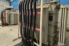
Description of installation
Incoming power supply details: Two of 6.6kV voltage lines are connected to the cracker plant from the distribution substation through reactors. Captive power plant (electricity generation facility) consists of two 36MVA gas turbine generators, two 5MVA steam generators, and two 33kV grids connections in floating mode.
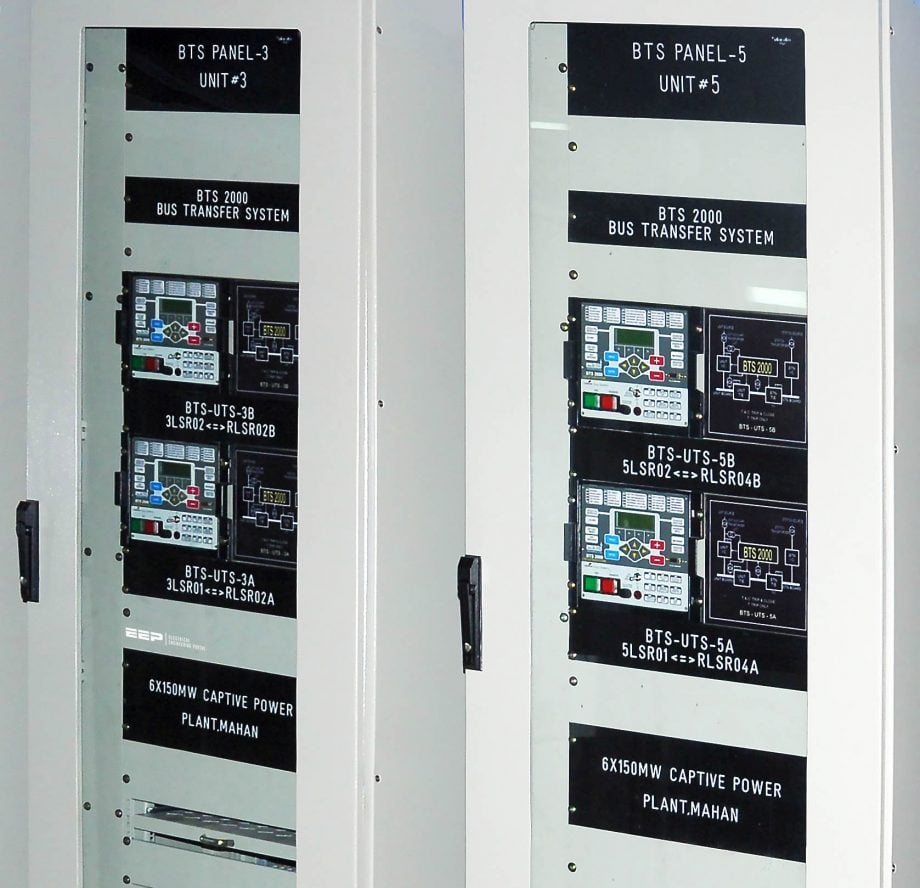
Load details: Four distribution transformers, six 750kW cooling water pump motors, four 630kW feed water pump motors, two 400kW quench water pump motors, and two oil quench pump motors are connected to plant load bus.
- Problem definition
- Solution for the above problems
- Inputs, initiation conditions and blocking interlocks
- Problems encountered during installations
- Advantages of high-speed bus transfer protection
1. Let’s define the problem
Problem #1
Cracker plant is the mother plant for the site, and continuity of power supply is an absolute priority. Though we have a captive power plant that ensures continuity of power most of the time, there are odd cases where the conventional auto-transfer scheme is operated, which resulted in a break in power supply and eventually resulted in a slowdown in production.

