
Estimated Study Time: 44 minutes
Substation Construction Drawings
Have you experienced “As Built” substation drawings that significantly differ from the original documents provided by the engineer for construction? Diverse factors cause these modifications in the field. However, in almost all instances, modifications to the design in the field negatively affect the project budget and timeline.
 Facing “As Built” substation drawings that barely match construction drawings
Although these alterations cannot be entirely eliminated entirely they can be mitigated by ensuring the substation design is constructed efficiently.
Even an expert design team may lack the required expertise and insight into the substation construction and installation process necessary to create a design that minimizes total installed costs, particularly when the component in question is a crucial element of a complex system like an electrical substation.
These essential phases ensure that the “constructability” of the facility and its components is thoroughly integrated into the design prior to implementation in the field.
- Field Construction Drawings
- The Origins of Drawing Changes in the Field:
- Why Applying Quality Assurance/Quality Control (QA/QC)?
- Well Defined Substation Design Process: A Key to Success
- Define the Substation End State: Final Look and Operational Functionality
- Define the Project’s Scope: The Tasks
- Project’s Scope MUST Be Reviewed and Approved
- Developing Project Schedule: Extremely Important
- Developing Engineering Schedule
- Procurement Schedule: When Material MUST Be On Site
- Follow the Schedule (The Most Difficult Step)
- Post-Project Review
- Important Design Steps for Substation Constructability
- Team Selection: Required Skill Sets and Experience
- Conclusion
- Attachment (PDF
 ) – Substation Design, Construction and Inspection Guide (34.1 MB)
1. Field Construction Drawings
No project is finalized without annotations from the field on construction drawings. Occasionally, the annotations serve solely as guidance for the teams to execute the project. At other cases, the adjustments are necessitated due to the project’s inability to be constructed as originally designed.
This may lead to field-marked prints that significantly differ from the construction drawings provided. Similarly, no project is ever finalized without inquiries from the field.
Sometimes all it takes to ask a question is to make some confusion clear. At other occasions, concerns relate to the procedures necessary for construction or potential disruptions involving other substation equipment. Certain queries necessitate comprehensive investigations for resolution.
If engineering resources are committed to other projects, the time dedicated to addressing field inquiries or examining field-marked prints will adversely affect the timelines of those projects receiving those resources.
This article examines the core reasons of field changes, situations of avoided field changes, the purpose of the quality assurance/quality control (QA/QC) program, and the design process.
In addition, this technical article addresses the main constructability-related aspects of the design process, the skill sets needed to maximize constructability in the design, and the advantages of employing Engineering, Procurement, and Construction (EPC) companies for projects.
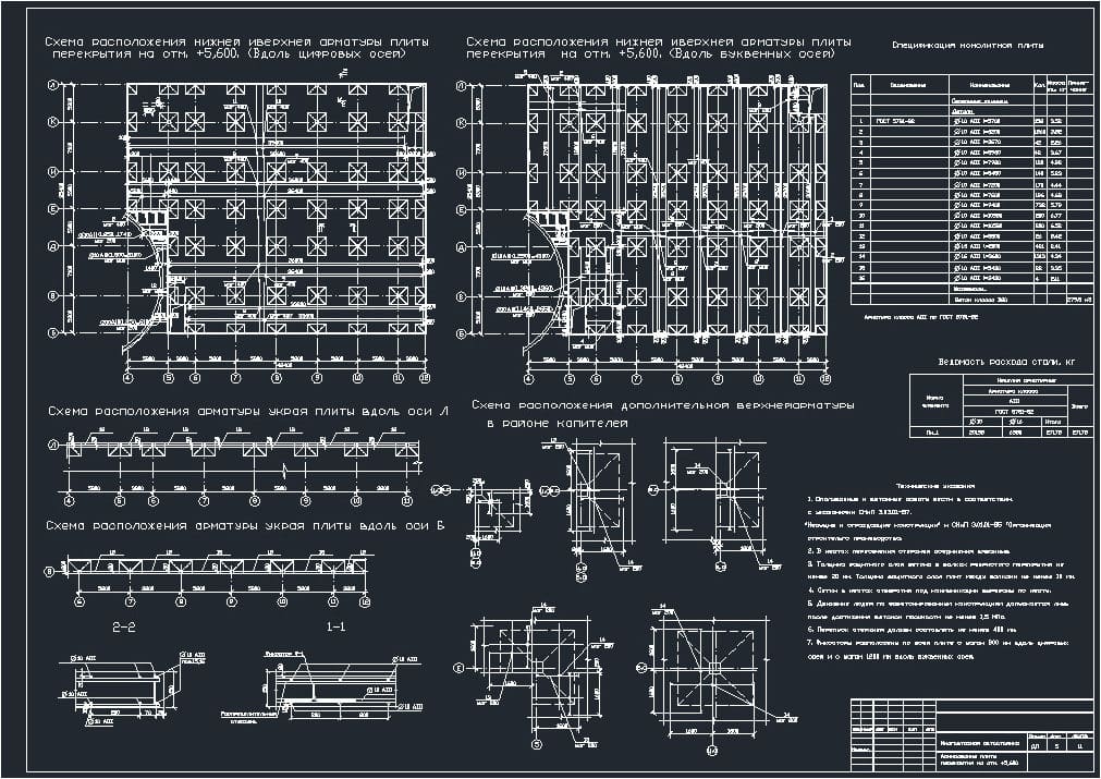
Figure 1 – An example of a substation construction drawing
2. The Origins of Drawing Changes in the Field
Understanding the reasons behind changes in the field is the first step in discussing and developing a QA/QC program or a substation design process. Reviewing a wide variety of projects has revealed that there are usually three main causes:
- Ignoring the need to check existing blueprints or actual physical conditions when designing.
- Designing without an understanding of construction practices.
- Designing without following a QA/QC program or adhering to a proven design process.
2.1 Drawings Do Not Match Real World
A widespread reason for modification in the field is the discrepancy between the design drawings and the actual conditions of the project site at the time of construction. This is particularly relevant on brownfield areas. The drawings may not have been revised to account for the installation or removal of equipment.
This kind of situation may occur due to the failure to include field modifications from a prior project’s construction into the record drawings, or because field-marked prints were not communicated to the engineering department.
Such issues can be resolved by field-verifying the drawings intended for the design.
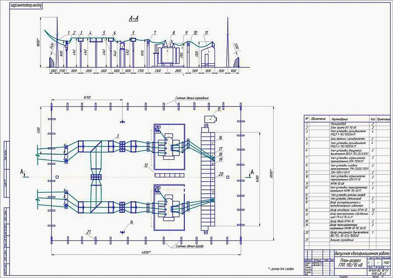
Figure 2 – “As built” switchyard layout drawing often differs from origin design plan
2.2 The Ethernal Battle: Theory vs. Practice
A widespread reason for changes in the field is the design of a substation project based solely on theoretical considerations, neglecting the practical methods used in project construction. Designers generally create with the intended final outcome in mind. Designers typically do not consider the construction processes necessary to attain the planned final outcome.
This scenario directly connects to the absence of construction or field experience among the designers, demonstrating the practice of designing substation without consideration for constructability. Substation designers must meet with the relevant construction experts to discuss on the design and construction approaches.
An instance of design neglecting construction practices is the design of a 3-conductor #500 kcmil system. The concept is straightforward; but, the physical installation of 3-conductor #500 kcmil cable is very challenging.
An instance of design neglecting the necessary building procedures might be illustrated by the replacement of three transformers. Replacing the transformer appears straightforward: remove the existing transformer and illustrate the new one.
Nevertheless, adding practical considerations into the scenario, such as the necessity for three operational transformers during construction and the absence of sufficient real estate for a fourth transformer, significantly complicates the design. The design is quite challenging without consulting engineers with construction and operational expertise.
Employing the suitable engineers in the scoping, planning, and design review process integrates theory and practice to build a robust strategy.
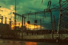
Figure 3 – Substation engineers with the theory knowlege and field practice is a key to the project success

2.3 Poor Drawing Quality
A significant factor influencing field changes is poor drawing quality. Substandard drawing quality include inconsistency in design, grammatical inaccuracies, improper cut and paste, citation errors, insufficient detail, and excessive information density. Those creating the designs may overlook some flaws.
Drawings serve as guidelines for constructing, maintaining, and troubleshooting the project. Weak instructions result in a waste of time and resources on construction, maintenance, and troubleshooting.
The quality of drawings results from QA/QC procedures. The significance of these methods will be elaborated upon thereafter.
2.4 Always Problematic: Project Schedule
No project manager wants to be informed that a project timeline is overly ambitious or unachievable. Remeber that the project timetable always significantly influences the quality of the project design. This, thus, influences the constructability of a project. An aggressive project timeline provides fewer opportunities for the QA/QC procedure to be effectively executed.
An rigorous project timetable significantly restricts the timeframe for the timely receipt of vendor or subcontractor drawings, which is essential for the completion of additional engineering drawings.
Related electrical guides & articles


Edvard Csanyi
Hi, I'm an electrical engineer, programmer and founder of EEP - Electrical Engineering Portal. I worked twelve years at Schneider Electric in the position of technical support for low- and medium-voltage projects and the design of busbar trunking systems.I'm highly specialized in the design of LV/MV switchgear and low-voltage, high-power busbar trunking (<6300A) in substations, commercial buildings and industry facilities. I'm also a professional in AutoCAD programming.
Profile: Edvard Csanyi
