
Estimated Study Time: 17 minutes
Switchyard Design Facts
What do you need to know about designing a switchyard? Well, to simplify, you need a lot and it’s not that simple. Switchyards need to be designed with respect to the foreseeable voltage stress, switching, breaking and short-circuit withstand capability, loading under normal and emergency conditions taking account of the requirements of load dispatch management, operational security, and supply reliability.
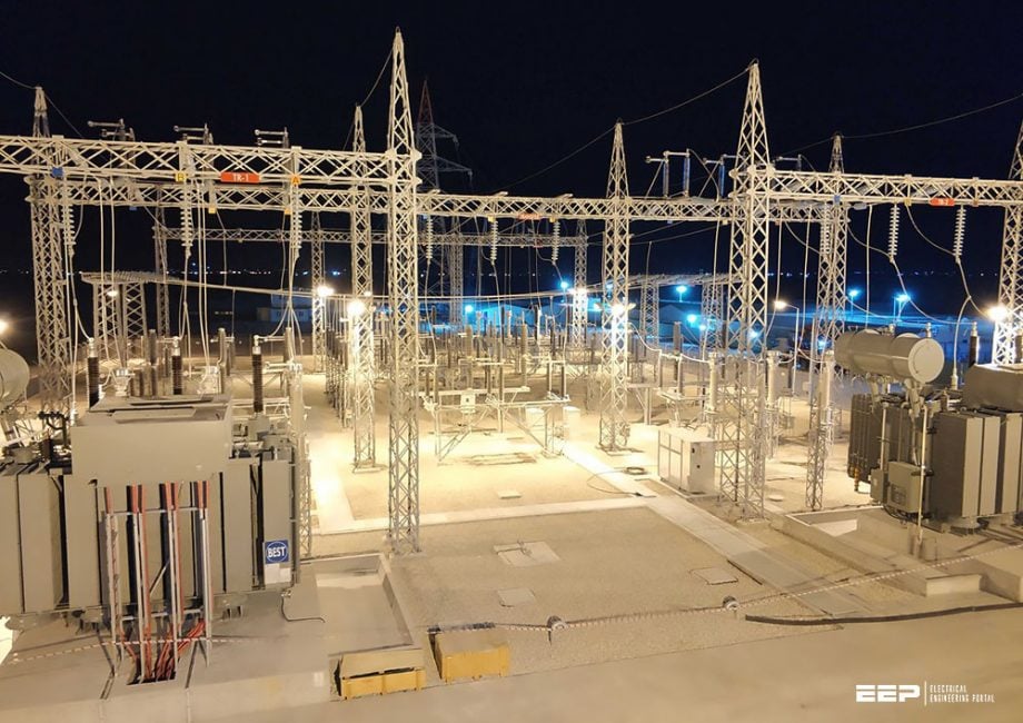 Switchyard arrangement and connection of incoming and outgoing feeders
However, this technical article does not deal with design details but switchyard design facts, so let’s start. As you already know, switchyard consists of many elements, and it would take many words and hours to name them all, but roughly we can group them into few groups:
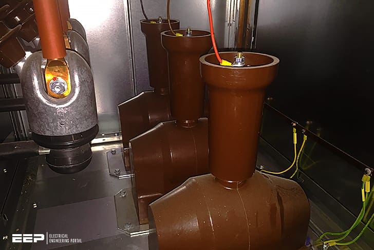
- Electrotechnical equipment such as switchgear, current and voltage transformers, surge arresters, insulation joints, armatures.
- Mechanical structural parts such as conductors, bars and pipes for busbars and gantries, partly seen as electrotechnical equipment as well.
- Secondary devices such as measuring and protection transformers and transducers, protective relays, coupling for remote control, batteries and so on.
- Civil engineering structures such as buildings, foundations, fire-extinguishing equipment and fences.
The documentation of switchyards becomes extensive when account is taken of the multiplicity of items of equipment, their interdependency and their importance. Knowledge of the appropriate standardized symbols according to the different parts of IEC 60617 is therefore necessary.
- Circuit Breakers and Switches
- Incoming and Outgoing Feeders
- Current Transformers
- Voltage Transformers
1. Circuit Breakers and Switches
The different types of breakers and switches to be used in switchgears are described in different parts of IEC 60947 and IEC 60890 for low-voltage installations as well as in EN 50052 and EN 50064 for high voltage installations.
Let’s remind ourselves of basics:
Fact #1 – Circuit-breakers have a switching capability for switching on and off any kind of current up to the rated current, that is, load current and short-circuit currents.
Fact #2 – Circuit-breakers installed in overhead systems should have the capability of operating sequences for successful and unsuccessful autoreclosing.
Fact #3 – Load-break switches are capable of switching load currents under normal operating conditions, but have no capability for switching short-circuit currents.
Fact #4 – Disconnecting switches can be operated only under no-load conditions. Currents of busbars without load and no-load currents of transformers with low rating can be switched on and off as well. Interlocking with the circuit-breaker is necessary.
Fact #5 – Earthing switches are used for earthing of equipment. The combination of earthing switch with disconnecting switch is common.
Fact #6 – Fuses are installed in LV and MV systems only. They interrupt currents of any kind by the melting of a specially designed conductor and must thereafter be replaced. Combination of fuses with disconnecting switches can be found especially in LV systems.
Circuit-breakers are named according to the method of arc quenching they use. Vacuum circuit-breakers are nowadays installed in MV systems. In the HV and EHV range outdoor circuit-breakers are operated with compressed air or sulfur hexafluoride (SF6). Circuit-breakers in gas-insulated switchgear (SF6-isolated) are of the SF6 type.
Recommended reading (paper, PDF): Fundamentals of High Voltage Circuit Breakers, Switching Stresses and Failure Modes
2. Incoming and Outgoing Feeders
Incoming and outgoing feeders in switchgear are equipped with circuit-breakers and disconnection and earthing switches. Current and voltage transformers for the connection of protection and measurement devices are usually installed at each feeder in HV switchyards.
In addition, the feeders are equipped with surge arresters and coupling devices for frequency carrier signals depending on the requirements of the switchgear.
A typical arrangement of the individual devices of feeder arrangement in a HV switchyard is outlined in Figure 1.

Where:
- Busbar disconnecting switch,
- Circuit-breaker,
- Feeder disconnecting switch,
- Earthing switch,
- Current transformer,
- Voltage transformer,
- Capacitive voltage transformer with coupling for frequency carrier signal,
- Blocking reactor against frequency carrier signals.
3. Current Transformers
Current transformers are used for the connection of protection and measuring devices. In order to avoid damage by high voltages, current transformers are not allowed to be operated without load and must not be protected by fuses on the secondary side.
One terminal of the current transformer on the secondary side is to be grounded for definition of ground potential. Current transformers are named according to the intended purpose (M: Measurement; P: Protection) and accuracy. For measuring purposes, accuracy classes 0.1, 0.2 and 0.5 are used.
The total measuring error remains below 0.1%, 0.2% and 0.5% if the current transformer is operated in the range of 100–120% of the rated current. Current transformers with accuracy classes 1, 3 and 5 (accuracy 1%, 3% and 5%) are used for operational measurements.
The rated overcurrent factor nr defines multiples of the rated current at rated load Sr and power factor cosϕ = 0.8 of the load (burden), for which the error remains below the value defined in the accuracy class. For measuring purposes, overcurrent factors of nr < 5 are sufficient, while the overcurrent factor for protection purposes should be nr > 5–10.
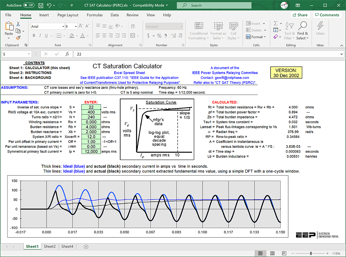
Current transformer (CT) saturation calculator (MS Excel Spreadsheet .xls):
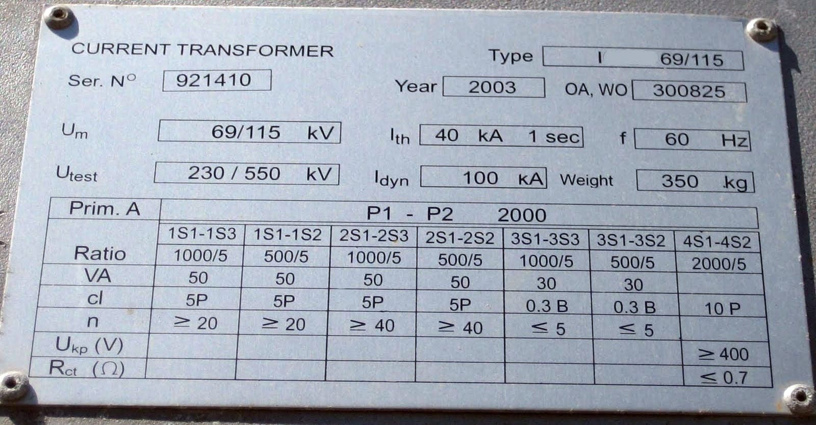
The total error is indicated according to IEC 60044 as for the accuracy class, for example:
- 40 VA 5 P10 Rated load (burden) 40 VA:
- Protection current transformer P;
- Total error below 5% with the rated overcurrent factor nr = 10
- 30 VA 0.5 M5 Rated load (burden) 30VA:
- Measuring current transformer M;
- Total error below 0.5% with rated overcurrent factor nr = 5.
The total error is given by the geometric addition of magnitude error Fi and the phase-angle error δi, if the instantaneous values of the primary and secondary current are taken into account for the determination of the total error.
With reduced burden SB, the overcurrent factor increases in accordance with the following equation:
Figure 2 represents the error of a current transformer for different rated overcurrent factors and different burden. Current transformers have to withstand the expected short-circuit currents. The withstand capability is determined by the rated short-time current Ithr and the rated peak short-circuit current ipr.
Apart from the measuring error of the current transformer, the transient characteristic of short-circuit currents with maximal DC component and the magnetic remanence flux remaining in the core after disconnection of short-circuits are of significance.
In automatic reclosing it is possible to switch into the still-existing short-circuit, with the consequence that the remaining remanence flux in the current transformer leads to a very high magnetizing current, driving the core into saturation and thus impairing the performance.
IEC 60044 additionally defines the current transformer class PR with special requirements on the remanence flux. The ratio of remanence flux to saturation flux (remanence factor Kr) may not exceed 10%.
An increased transformation ratio with reduced burden must be avoided with respect to difficulties with protective excitation. Requirements for the transient characteristic of current transformers are defined in IEC 60044. The requirements are realized by a linearization of the iron cores: four categories are defined, as specified in Table 1.
Table 1 – Categories of current transformers and their parameter according to DIN EN 50482 and DIN EN 61869.
| Category | Implementation | Fi | δi | Kr | Ts |
| P |
| – | – | – | – |
| TPS |
| ±0.25% | – | – | Some seconds |
| TPX |
| ±0.5% | ±30′ | ~0.8 | Some seconds |
| TPY |
| ±1.0% | ±60′ | ~0.1 | 0.1s up to 1s |
| TPZ |
| ±1.0% | ±18′ | ~0 | 60ms |
The transfer from primary to secondary of the fundamental current (50Hz or 60 Hz) is achieved adequately with these current transformers; the transfer of the DC component is less with increasing linearization of the core.
4. Voltage Transformers
Voltage transformers are used for the measurement of line-to-line (phase-to-phase) voltages and line-to-earth (phase-to-neutral) voltages. Voltage transformers are constructed either as inductive transformers (Un = 1–765kV) or as capacitive transformers (Un ≥ 60 kV). Capacitive voltage transformers are suitable for the connection of frequency carrier signals.
Voltage transformers are named according to their intended application (M: Measurement; P: Protection) and their accuracy class. One has to take into account error in magnitude FU and phase-angle error δU. The indicated error margins are to be guaranteed with secondary burden of 25% and 100% of the rated burden at power factor cosϕ = 0.8.
The accuracy of measuring voltage transformers (class M) is to be guaranteed in the voltage range between 0.8 × Un and 1.2 × Un, and for protective applications the voltage should be 1.0 × Un.

Voltage transformers with classes 0.1, 0.2 and 0.5 (error less than 0.1%, 0.2% and 0.5% within the range 0.8–1.2 × Un) are used for exact measurement purposes. For operational measurement, voltage transformers with accuracy class 1 and 3 (error less than 1% and 3%) are used.
For protection purposes, voltage transformers 3P and 6P are used, having voltage error less than 3% and 6% and a phase-angle error less than 120 minutes and 240 minutes respectively in the voltage range 0.8–1.2 × Un.
Figure 4 indicates the dependence of the phase-angle error and the error in magnitude with different burden for a voltage transformer:
Single-pole isolated voltage transformers are exposed to increased voltages of varying duration depending upon the neutral earthing of the system. The rated voltage factor indicates multiples of the nominal system voltage.
The voltage transformer is allowed to be operated for times of 30 s, 4h or 8h. Voltage transformers with a rated voltage factor 1.5/30s may be used only in systems with low impedance earthing (earth-fault factor δ ≤ 1.4); those having a rated voltage factor of 1.9/30 s or 1.9/4 h or 1.9/8 h can be installed in systems with all kinds of neutral earthing, that is, isolated neutral, resonance earthing and low impedance earthing.
The factor 1.9 corresponds approximately to the maximal permissible voltage of the system (power frequency).
These transient oscillations downgrade the performance of distance protection relays, especially with respect to the direction decision.
The problem can be solved, however, by small load of the voltage transformer and/or by installation of a filter circuit. Furthermore, ferroresonances can occur with capacitive voltage transformers.
Recommended reading: Connection schematics of voltage transformers for protective applications
Source: Power System Engineering by Jürgen Schlabbach and Karl-Heinz Rofalski
Related electrical guides & articles


Edvard Csanyi
Hi, I'm an electrical engineer, programmer and founder of EEP - Electrical Engineering Portal. I worked twelve years at Schneider Electric in the position of technical support for low- and medium-voltage projects and the design of busbar trunking systems.I'm highly specialized in the design of LV/MV switchgear and low-voltage, high-power busbar trunking (<6300A) in substations, commercial buildings and industry facilities. I'm also a professional in AutoCAD programming.
Profile: Edvard Csanyi

Have been examining a 132/66kV substation layout drawing and came across to see the incoming 132kV only have one CVT installed connecting on the A phase while the other 2 phases B&C don’t have CVT installed. This is also applies to the outgoing 66kV with only one CVT connected to A phase and the other 2 phases are not.
Note; After the 132kV bus there are CVT each installed on each phase and the 66kV side as well.
With these type of layout arrangements, is it still ok?
Iam wondering, why the other 2phases for the incoming 132kV and outgoing 66kV don’t have CVTs each install?
I will appreciate if there are explanation to clear such layout intended for installations.
what type of CT and VT with class and accuracy are used for 1*25kv and 2*25 kv traction systems in traction substations (TSS) and sectioning posts (SP).What design factors shall be taken into consideration while designing a TSS
May I know how to calculate the stacking factors of 3-stepped and 4-stepped transformer cores?
I found the dimension drawings but I cannot reach the right answers. The name of the original text book is not shown.
Very informative article.
Since I am in the job of training staff in the Facility Management field, may I request if some more basic understanding with photos of the Sub-Station components could be shared to help the budding engineers in the FM field.