The Failure & Explosive Nature
Generally, the useful life of power system components heavily depends upon the level of care given to them and their duty cycles. For example, a circuit breaker on mainly switching duty can last 40 to max. 50 years. The majority of transformers at the utilities serve about 40 years if none of the catastrophic events such as lightening happen. On the other hand, on-line tap changers in HV transformers are prone to failure.

HV bushings are accounted for as one of the most significant single causes of failure in MV/LV substations. The failure mechanisms tend to develop to a critical level at a midlife point for the surrounding assets and such mechanisms generally result in a sudden and catastrophic failure of an explosive nature, thus significantly shortening the life span of HV substations.
- CB Bushing Failures In MV Switchgear
- Case Studies of MV Switchgear Failures
- Metal-Clad Switchgear Failures
- Failure of MV Power Cables
- Low-Voltage Switchboard Failure
1. CB Bushing Failures In MV Switchgear
Violent bushing failures in MV switchgear, if they happen, may cause catastrophic damage to the surrounding buildings and adjacent plants. For example, a significant number of such catastrophic failures are presented in a report from the City of Cape Town in South Africa.
Multiple failures began occurring after the manufacturers replaced previously used Bakelite paper bushings with resin cast bushings. The replacement was related to the expansion of SF6 and vacuum technology with the supposed advantages of resin cast technology. Resin cast insulators are considered have greater suitability for mass production, superior fault toleration, resistance to scratch, and mechanical damage resistance.
To fit them in the same panel as the older oil breakers, some manufacturers would redesign existing breakers to use SF6 and resin cast technology. South African utilities used three models of SF6 MV switchgear from the same manufacturer, which are all interchangeable with previous generation oil breakers.
However, contrary to the expectations, the City of Cape Town experience showed that bakelite paper bushings outperform resin cast bushings by far.
In 2004, the substation experienced a number of the earliest known failures in the City of Cape Town. Chlorine was strongly odorated when staff entered the substation for switching operations. Upon further inspection, they discovered that the breaker had severe discharge degradation on the bushing insulation and cluster contacts. At the substations, there was also severe corrosion, tracking, and cluster degradation (Figures 1 and 2).
Figure 1 – Failed breaker with severe discharge degradation on bushing insulation and cluster contacts


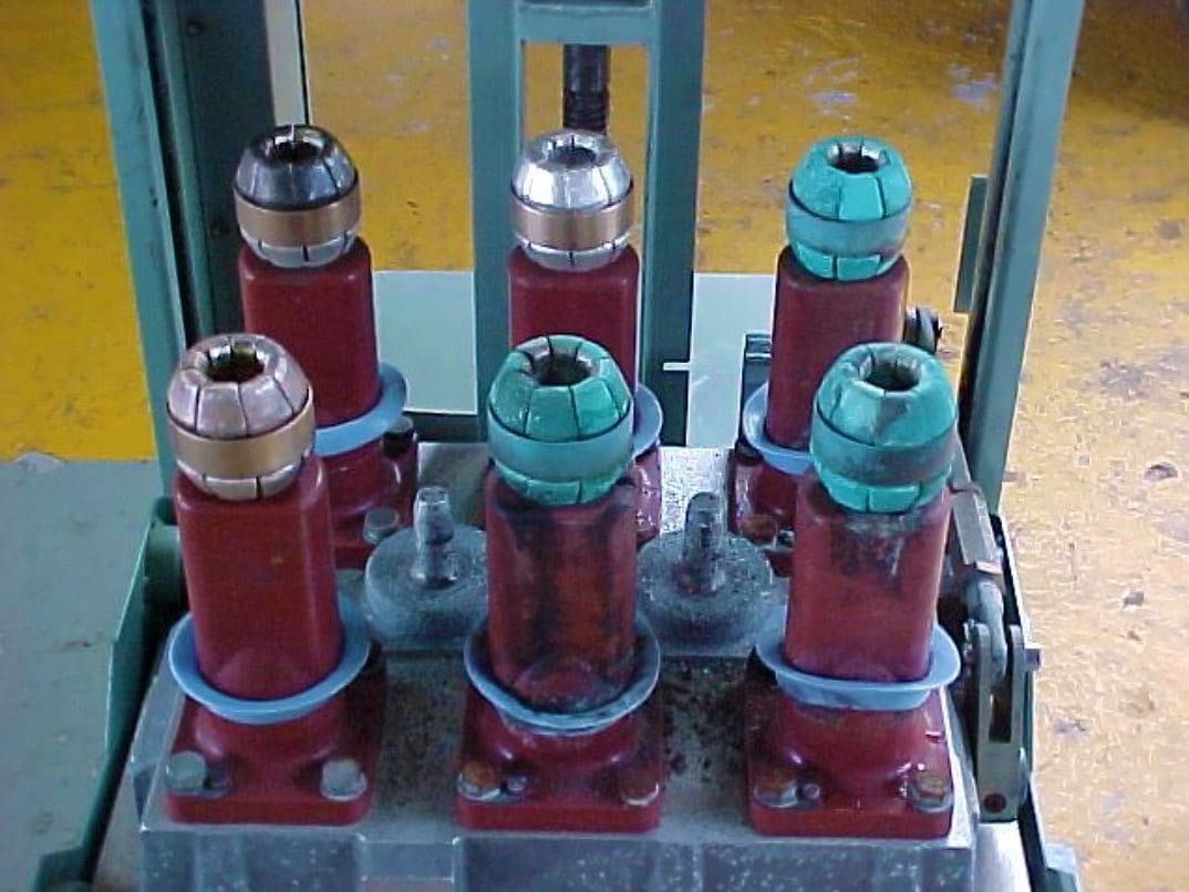
Figure 2 – Another case of degradation of CB clusters and bushings


During inspection, other defects have been found, such as pores beneath the skin of the bushing resin (manufacturing defects), as well as misalignment of shutter boxes (signs of poor quality control during manufacturing).
Based on inspection results and root cause investigation, severe partial discharge activity was determined as the primary cause of failures. The probability of partial discharge activity was increased due to multiple local regions of electrical stress created within voids, pores, and bubbles in resin moldings.
However, while most of the new switchgear panels are fitted with heaters, some manufacturers specify panel heaters as optional.
Misalignment of the breaker may play a significant role in increased partial discharge activity. Because the shutter box apertures are positioned unevenly, the electrical field around the bushing is inconsistent if the breaker bushings and the corresponding orifice bushings are out of alignment. The same result could be achieved by misaligned shutter boxes.
Breakers that are not aligned properly run the risk of damaging the orifice (female) bushing and tracking. Operating these breakers might be risky.
Figure 3 – Severe corrosion degradation of circuit breaker clusters


Figure 4 – Severe corrosion degradation of circuit breaker and tracking on the bushings


Go back to the Contents Table ↑
2. Case Studies of MV Switchgear Failures
The MV switchgear failures can be attributed to inadequate design. However, inadequate maintenance procedures that fail to stop and identify mechanical and electrical issues that cause failures are more frequently to blame for failures. Increased load densities also put a great deal of strain on the infrastructure of the current, outdated MV switchgear.
Solutions frequently make an effort to balance the competing demands of upholding high availability and reliability while keeping costs down and offering the highest levels of safety.
Errors in design, defects of the components, and human mistakes, and a combination of all these, may cause severe MV switchgear failure.
2.1 Case #1: Component Defect
The following failure happened with a feeder breaker, which was taken out for performing CM tests. The breaker was racked in the “test” position and the wires for the timing test were attached to the arms of the breaker. When inserted in the “test” position, the breaker flashed over. It was discovered that the mechanical interlock’s failure was what led to flashover.
The test equipment’s metallic clamp came within arcing range of the live busbar when it was connected to the breaker, which led to the flashover.
Suggested Reading – Why remote racking of LV/MV circuit breakers is a smart investment but so rare to see?
Why remote racking of LV/MV circuit breakers is a smart investment but so rare to see?
Go back to the Contents Table ↑
2.2 Case #2: Arcing and Breaker Design Errors
During fault clearance, the medium voltage breaker malfunctioned, severely damaging the switchgear room’s doors and windows. Following a root cause analysis, it was determined that during breaker failure, the arc created a pressure wave that was unable to escape, damaging the door and windows.
If the outlets for the pressure wave had been installed in the switchgear room at various points as hinged louvers, this damage might have been avoided. Normal operation keeps these louvers closed, keeping outside dust from entering the room.
When an electrical arc creates a pressure wave, the pressure is released through these louvers, protecting the switchgear room and the operating personnel who are present in the room from harm.
Figure 5 – Medium voltage circuit breaker arcing damage


Go back to the Contents Table ↑
2.3 Case #3: Flashover and Water Condensation
A feeder that was charged and carrying no current experienced a flashover in the breaker compartment. It was found that the space heater in the breaker compartment was defective (manufacturing defect).
Condensation in the breaker compartment would be reduced as a result. As there was water condensation in the compartment as a result of the heater being off and the load current being zero, flashover occurred.
Suggested Reading – Be extremely careful when racking in and racking out circuit breaker
Be extremely careful when racking in and racking out circuit breaker
Go back to the Contents Table ↑
2.4 Case #4: Operational Instructions Not Updated
Serious arc flash incident results in equipment damage
A worker was carrying out a process (not electrical) isolation related to routine pump maintenance. A significant arc flash and blast occurred when the medium voltage (MV) 3.3 kV isolator was switched, partially opening the switchgear control cabinet door. There was a risk of the worker suffering a serious injury in addition to the switchgear equipment being damaged.
The worker was fortunate to be wearing Category 4 arc blast-rated personnel protective equipment, which included hearing protection, and to be unharmed physically.
Although the active front end had recently been added to the installation, the operational instructions had not yet been revised to account for this retrofit.
Figure 6 – Switchgear panel with front and rear panels removed and damage from the arc blast. See the condition of the busbars that are broken


Probable causes:
Direct:
- Although the main isolating switch was intended to be activated once the variable speed drive (VSD) contactor had opened, the isolation was carried out while the contactor was still closed and reactive current was still flowing.
- The main isolating switch was not intended to break the highly reactive current flow, so it was unable to do so.
Indirect:
- It was possible to operate the isolator while the contactor was still engaged because a mechanical interlock between the two devices malfunctioned.
- The switchgear cabinet did not contain the arc blast protection.
- The design and operation requirements for this type of drive were not taken into account during the switching process.
Go back to the Contents Table ↑
2.5 Case #5: Breaker Overheating
An MV vacuum circuit breaker (22 kV, 2500 A) failed during service. Following a failure analysis, it was thought that the breaker’s current-carrying component had overheated while supplying the nominal load current. The overheating was proved by carrying out a Heat Run test, which showed that the TR was exceeding allowable limits.
To prevent overheating with the breaker inside the cubicle, a derating factor of 20% had to be applied, especially for feeders that carry more than 70%–75% of the breaker/switchgear-rated current.
Suggested Reading – How to design a fault-tolerant & reliable facility distribution system
Key points on how to design a fault-tolerant and reliable facility distribution system
Go back to the Contents Table ↑
3. Metal-Clad Switchgear Failures
Let’s discuss about two failure cases of metal-clad switchgear, one at the U.S. Nuclear Generating Station (NGS) and another at a foreign nuclear power station (NPS). The most intriguing feature of both incidents was how an electrical fault in one breaker cubicle spread damage to other breakers and buswork in the same enclosure.
These electrical occurrences help us understand potential collateral damage, cascading failures, and plant operation challenges that could result from a single electrical failure.
3.1 Case #1: Failure of the 25-Year-Old CB and Lack of Maintenance
A fault on a 4.16 kV supply CB from the unit auxiliary transformer led to a fire and the loss of offsite power while shifting loads to the unit auxiliary transformers. The 4.16 kV breaker’s C phase main contacts didn’t completely close, which was the root of the problem. This resulted in arcing and the production of a thick, dark ionized smoke. The breaker was a three-pole, MV AC power CB rated for 3000 A (continuous) and 350 MVA (interrupting).
The breaker had undergone its last preventive maintenance four years before it failed, and it was about 25 years old. The extensive fire damage made it impossible to pinpoint the exact reason why the breaker didn’t close.
Figure 7 – AC Power Distribution System with Y Connection to Safety Buses


Ionized smoke, which is conductive, diffused through conduits and holes between adjacent cubicles, cutting off off-site power. The energized incoming terminals of the offsite power supply from the backup auxiliary transformer were shorted as a result. The fault blew off the insulating boot that covered the A phase busbar and the cubicle door of the offsite supply CB.
The HV supply breakers upstream of the reserve auxiliary transformer opened to clear the fault. This interrupted the non-vital offsite power to the unit. Due to the loss of off-site power, DC backup power was required to run the turbine lube oil pump without regard to safety.
The main turbine sustained significant damage as a result of the DC supply breaker for the lube oil pump failing.
Go back to the Contents Table ↑
3.2 Case #2: Insulator Failure
At a foreign nuclear power station, a fault in a 4.16 kV load center caused a fire and the loss of offsite power, while the reactor was shut down but with significant decay heat. This led to a station blackout, which was brought on by a subsequent independent failure in the onsite standby power supply (i.e., a loss of AC power to both redundant safety systems).
Recovery from the event was further complicated by smoke and the dependence on AC-powered emergency lighting and ventilation.
The 345 kV transmission system’s insulators had salt deposited on them from days of foggy, misty weather, which resulted in power fluctuations and outages. The 345 kV transmission system had been disrupted the day before the failure, which led to an automatic reactor shutdown and transfer to a backup 161 kV offsite source.
On the day of the failure, the 345 kV source was recovered, and the circuit into the plant was reenergized with the reactor shut down and the unit receiving offsite power from the 161 kV backup source.
After the switchyard 345 kV CB was closed (energizing the 345/4.16 kV transformer and the 4.16 kV circuits into the vital load centers, while the 4.16 kV supply breakers were still open), a fault occurred in the A train 4.16 kV load center. The fault was caused by insulator failure on one phase of the A train 4.16 kV safety-related switchgear on the supply side of the supply breaker from the 345/4.16 kV transformer.
Both trains lost all power due to an unrelated failure of the other onsite power source. Additionally, the backup station’s blackout power supply was disabled due to the loss of off-site power.
Suggested To Study – Technical specification for construction of 33/11 kV 2×31.5 MVA substations
Technical specification for construction of 33/11 kV 2×31.5 MVA power substations
Go back to the Contents Table ↑
4. Failure of MV Power Cables
There are several factors causing the failure of medium voltage (MV) power cables. The types of insulation of cables that are most widely used lately are PE (XLPE, tree-retardant cross-linked polyethylene [TR-XLPE], and high molecular weight polyethylene [HMWPE]) and ethylene propylene rubber (EPR). Several causes of underground power cable failures have been defined, such as excessive pulling tension, water treeing, and corrosion.
HV surges may blow holes in the jacket and damage the shield, and water may enter through the holes and cause corrosion.
MV power cables are often located in inaccessible locations such as conduits, cable trenches and troughs, duct banks, underground vaults, or in other directly buried installations; under such conditions, they can fail due to insulation degradation.
Very often, partial discharge activity in power cables causes the failures. partial discharge is accelerated by various defects, such as voids, shield protrusions, contaminants, advanced stage of water trees, and so on. Partial discharges will gradually degrade and erode the dielectric materials, eventually leading to the final
breakdown.
Suggested Video – Webinar Medium Voltage Cable Failures Root Causes and Online Detection
Some of the causes of cable faults are as given below:
- Ageing,
- Corrosion of sheath,
- Electrical puncture,
- Moisture in the insulation,
- Heating of cable,
- Fire and lightning surges,
- Damage while in use due to excavation works, or
- Damage during laying.
Go back to the Contents Table ↑
4.1 Example of Failed Cable #1
The first example explored is an 11 KV PICAS to XLPE Branch adapter that failed one hour after installation. After investigation, the proximate cause was determined to be an incorrect positioning of the adapter tubes. Alternately, workmanship errors were determined to be the ultimate cause of failure.
Throughout the investigation, many quality issues were found. Shear bolts were misaligned, there was no putty in the shear bolts, the tubing was poorly cut and there were gaps in the insulation throughout the sample. Recommendations common for these conclusions include retraining the jointers and assessing the components done as a part of this project.
This example highlights that finding and fixing the one proximate cause of the failure is not adequate. There were several mistakes that all would have led to failure had the first cause not been present. By addressing the ultimate cause of jointer training, all of the workmanship issues and potential failure points would be addressed.
Figure 8 – XLPE/PICAS joint failed


Go back to the Contents Table ↑
4.2 Example of Failed Cable #2
The next example explored was a 33KV XLPE joint that failed after 18 months in service. The fault hole is visible through the insulation in the Figure 9 below. The failure occurred because a connector was not properly deburred by the jointer. The sharp edge caused mechanical damage and created a concentration of electric fields in the damaged insulation.
The takeaway for this failure was that poor understanding of instructions, lack of attention to detail, and lack of training all contributes to the failure of this joint.
Figure 9 – Failure location on 33KV XLPE joint


Go back to the Contents Table ↑
4.3 Example of Failed Cable #3
The final example explored is a Paper Insulated Lead Covered (PILC) cable that failed after 47 years of service (nice age btw!). The 11KV cable experienced a mid-cable failure as seen in Figure 10. This failure is a result of age related partial discharge. Although this cable was in service for an appropriate life span, this is an example of how partial discharge mapping could have prevented an unplanned failure.
Catching the partial discharge earlier would have allowed the client to plan an outage to address the issues.
Figure 10 – Failed Paper Insulated Lead Covered (PILC) cable


With cable failures costing clients significantly every year, identifying trends in occurrences can help reduce the future failure related costs. Forensic analysis allows for the community to learn from past failures to promote a more reliable and robust system.
The following conclusions were drawn from the investigation of 73 forensic analysis reports:
Conclusion #1 – Cable faults follow a predictable reliability curve and generally can be expected to fail within the first 10 years or after 40 years in service. With about 35% of failures occurring in the first ten years, it is vital that they are installed carefully to prevent the majority infant mortality related faults.
Conclusion #2 – By ensuring that installations are done following clear and accurate manufacturer’s instructions, 2/3 of faults could be prevented.
Conclusion #3 – Since human error is inevitable in every field, a proper asset management program founded on partial discharge testing can help identify and prioritize issues as they develop.
Although universal trends have been shown through these reports, these do not necessarily indicate that every company should prioritize the recommendation in the same manner.
Suggested Guide – Handbook on EHV overhead lines and underground cables
Go back to the Contents Table ↑
5. Low-Voltage Switchboard Failure
Let’s take the case of the switchboard failure occurred in a community infrastructure-related facility. The damaged switchboard (see Figure 11) had a supply bus rating of 1250 A, a section bus rating of 1250 A, and a neutral bus rating of 630 A. The switchboard short circuit rating was 25,000 A. The system was three-phase, four-wire, 480/277 V.
A physical inspection covered the switchboard, the main breaker, the bus, the metering compartment, and another bus nearby. The arcing damage was found primarily in the main breaker cubicle, vertical bus, and the metering compartment above the breaker.
The inspection revealed corrosion within the failed breakers and their connections, as well as on the nearby breakers. It was found that hydrogen sulfide was present in the air of the breaker’s electrical room. Over time, the hydrogen sulfide caused corrosion and flaking of the finger cluster surfaces. This gas also attacked the mating surfaces of the breaker cubicle bus connections (stabs), so they too corroded and flaked.
Figure 11 – Failed Low Voltage switchboard


The following chain of events was suggested to cause the failure:
About 20 days prior to the failure, electricians racked in the main breaker. Because the contact surfaces of its finger clusters and stabs were irregular and corroded, electrical connection had higher than normal electrical resistance. Load current passing through these connections produced extra heat, which accelerated further oxidation and deterioration of the connection surfaces.
That, in turn, worsened the heating problem. The heating will likely be most intense on the center (B) phase, and it was enough to melt the B phase connection surfaces. The normal load current produced an arc that bridged across the small gap where the copper surfaces had melted.
Melted wiring insulation may have allowed separate phases to make contact, or the melted fuse block may have similarly allowed separate phases to make contact. The control wiring short circuit was on the line side of the breaker and the line side of the control wiring fuses, and consequently did not cause the main breaker to open or the fuses to blow.
Suggested Course – Learn to Read and Analyze CB Schematics & Control Wiring Diagrams
Learn to Read and Analyze Circuit Breaker Schematics and Control Wiring Diagrams
Go back to the Contents Table ↑
Sources:
- Transmission, Distribution, and Renewable Energy Generation Power Equipment Aging and Life Extension Techniques by Bella H. Chudnovsky
- Mines Safety Significant Incident Report No. 191 – Serious high voltage (HV) arc flash incident results in equipment damage
- Bushing Failures In Medium Voltage Switchgear by C van Heerden : Certificated Engineer – District Manager, City of Cape Town and A. Rogerson BSc – Senior Consultant: Substation Assessments at EA Technology Services
- Information Notice 2002-01: Metalclad Switchgear Failures and Consequent Losses of Offsite Power by United States Nuclear Regulatory Commission Office Of Nuclear Reactor Regulation 20555-0001
- Review of Medium Voltage Asset Failure Investigations – William Higinbotham, EA Technology LLC Kelly Higinbotham, University of Connecticut
Related electrical guides & articles
Premium Membership


Very good article, thank you.
Very useful site for me as electrical engineer
VERY INFORMATIVE AND VERY GOOD CONTENTS