Generator‘s Field Winding
Generator field winding is an integral part of the generator set which is responsible for generating the magnetic field that induces the stator emf when the rotor rotates. Regulation of current in this winding with the help of an AVR (Automatic Voltage Regulator) allows for a smooth control of generator voltage and reactive power output. It is a low voltage DC current carrying winding wound on the rotor.
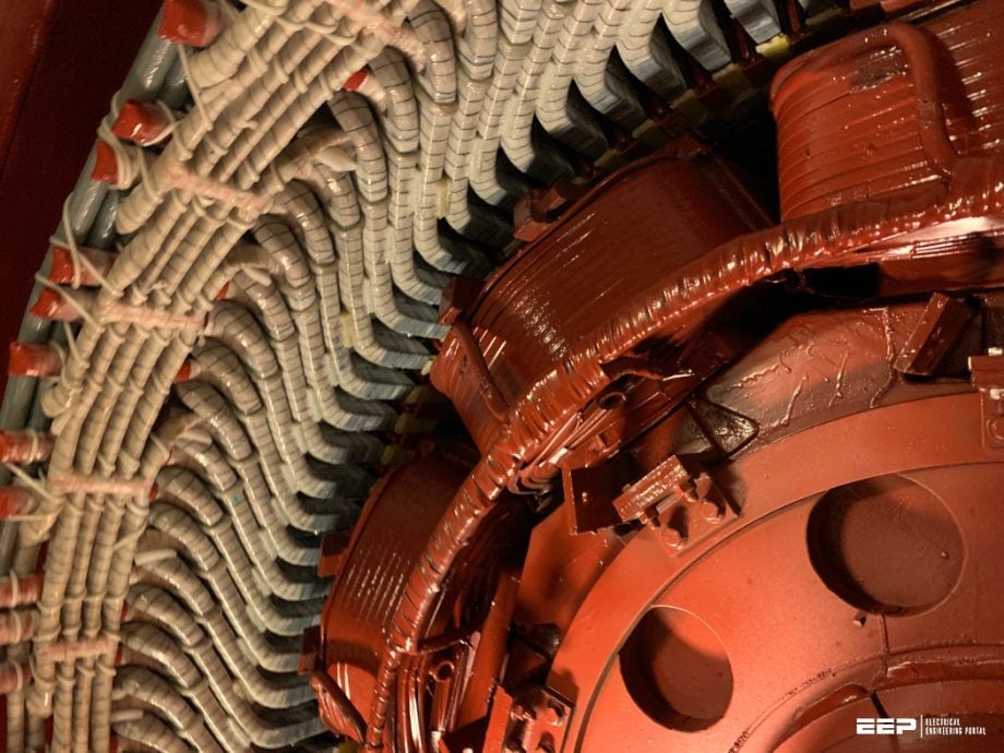
Hence, monitoring the insulation integrity of this winding requires altogether a very thoughtful approach and a sound interpretation of testing results.
Failure Scenarios:
During operation, field winding can run into either an open circuit or a short circuit with ground (more commonly known as the field ground) situation. An open circuit is the severe case of loss of excitation and can potentially result in catastrophic events for the generator and the system to which it is tied, which we will further explore in detail later in the article.
Similarly, field ground at one point is the beginning and if followed with field ground at two points, it could seriously jolt the entire system.
Arrangement of Field Winding:
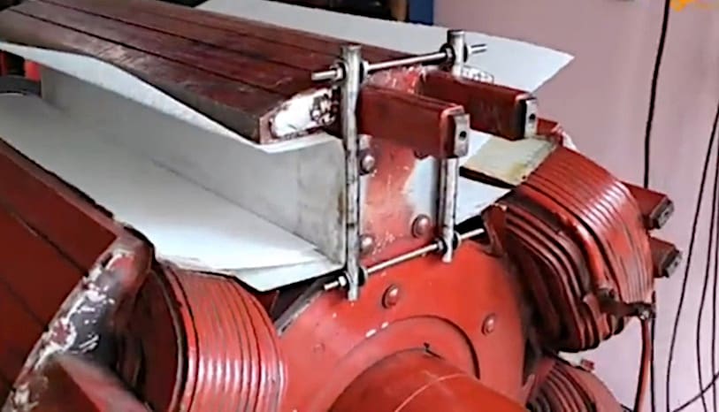
Figure 1 depicts the manner in which the field winding is wound around a rotor. The winding is further insulated from the protruded poles with an insulation paper between them. It is here that any failure of the field winding insulation results in field ground since the shaft of the machine is grounded through a ground brush.
Figure 1 – Winding of a 4-Pole Rotor

Consequences of Field Winding Failure:
Open circuit
Open circuit in the field winding drops the field current to zero (complete loss of field), although field current may drop to zero for other events as well such as AVR malfunctioning, terminal reference PTs and CTs or rotating rectifiers’ failure but we will keep our discussion limited strictly to the failures associated with the field winding and associated slip rings.
In case the field is open circuited while the generator is operating in parallel with the system, the system in an attempt to keep the generator voltage from dropping injects VARs into it and the stator currents increase. Increase in stator current and VARs injected depend upon the loading of the generator prior to the loss of field.
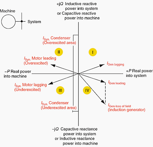
It now effectively starts turning as an induction generator (refer Figure 2) with a slip between the rotor and the synchronous field.The resulting slip induces slip-frequency currents in the rotor forging, retaining rings and wedges causing further damage due to overheating.
Figure 2 – Four Quadrant Power

Short Circuit/Field Ground
Short Circuit/Field Ground on solitary location isn’t so threatening as no part of generator excitation system is grounded, therefore, there is no flow of ground current yet it indicates the failure of field winding insulation. As a result, shorting from another location can follow almost the same consequences as discussed for open circuit since now a portion of field winding will be by passed by current flowing through the ground.
This will give way to unbalance in the airgap between the rotor and the stator. Consequently, there will be unbalanced magnetic force on the rotor creating torque pulsations which would lead to excessive vibrations of the unit travelling back up to the turbine.
Although, now the length of field winding by passed by the two field grounds is a deciding factor in determining the extent of damage. Similarly, the effect of turn-to-turn short circuit depends on the extent of winding being bypassed.
Detection of the Field Ground:
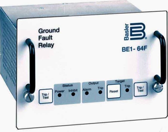
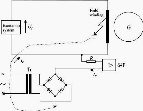
Field ground relay 64F is employed for the detection of field ground which usually measures the insulation resistance of the field winding with respect to the ground. Many utilities have two thresholds for low insulation resistance of the field winding; one for alarm and the other for tripping. However, in some cases the units utilize only single threshold directly for tripping in which case one isn’t alarmed about the deteriorating situation.
The latter approach maybe suitable to the units having brushless excitation where we have no slip rings exposed to the atmosphere (reason discussed next) or if time to time testing results have been more than satisfactory and no dramatic failure is expected.
Figure 3 – Field ground relay 64F

Operation on Single Point Ground Fault:
There may be times when the utility faces a scenario in which it cannot afford the loss of a unit and might be having to operate the unit on single point ground fault. The unit can be operated in that case but extreme care is required since we know now that the ground is set for the second fault to set in and cause extensive damage.
Still following measures could be taken to operate the unit when faced with such a situation:
- Disable the tripping against the field ground fault.
- Make sure the generator has loss of excitation protection enabled.
- Decrease the trip set point of the bearing vibrations so that the unit is tripped before the vibrations escalate from a second ground fault.
- After starting the unit to full speed no load, observe the generator excitation current and the corresponding terminal voltage.
- After synchronization with the system, the loading on the generator should be kept lower than normal as the extent of severity due to loss of excitation resulting from second ground fault depends heavily on the loading of the generator prior to the fault.
- Keep monitoring the excitation current of the machine.
In case there is any increase in the field current for a given load, the turbine should be tripped manually before the vibrations worsen (tripping the breaker first could overspeed the unit). For that little period, due to the removal of prime mover, the unit may now operate, depending on the state of excitation as synchronous motor (under excited), synchronous condenser(overexcited) or induction motor (no excitation) and trip against reverse power or be tripped manually.
However, if serious two-point grounding transpires, the unit would itself trip against loss of excitation.
Relaed Study – Six differential stator-phase-fault protection (87) for all size generators
Six differential stator-phase-fault protection (87) for all size generators (you MUST know)
Causes of Failure:
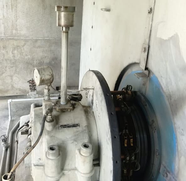
In most units, the problems start from the faulty breather mounted on the non-drive end bearing housing that abnormally lets out the fumes which end up collecting on the slip rings (rotating just next to it) and attract further dirt from the atmosphere. The collection of moist or carbonized dust hinders the contact between the carbon brushes and the slip rings and results in sparking between them.
The sparking leads to grooves on the slip rings surface and the brushes start bouncing which further leads to the formation of grooves at the pivot point of the carbon brush holders thereby loosening the tension of the carbon brushes against the slip rings surface and affecting the flow of field current.
Figure 4 – Grooves on Slip Rings Surface
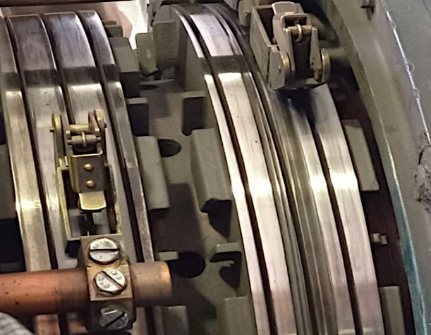

Figure 5 – Grooved Pivot Point of Brush Holder
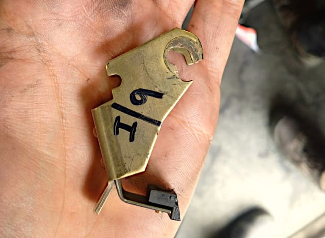

Not only that, collection of dirt on/around the slip rings assembly decreases its insulation resistance, where it has been observed that it improved following a cleaning operation. The proximity of bearing housing, particularly, the fiber sheet insulating the brush holder rocker arm from the bearing assembly should be checked for any oil seepage from the bearing which might flow towards the slip rings creating potential contaminated leakage paths.
Slip rings should also be inspected for excessive carbon deposits wearing down from the brushes. Lack of appropriate contact between the brushes the slip rings could drive the generator towards under-excitation where it may fall out of synchronism.
Figure 6 – Slip Rings Arrangement
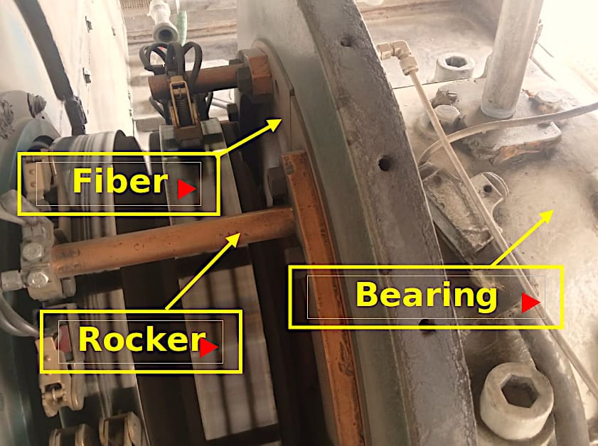

Figure 7 – Breather Mounting

Dust/Moisture with Ventilation Air:
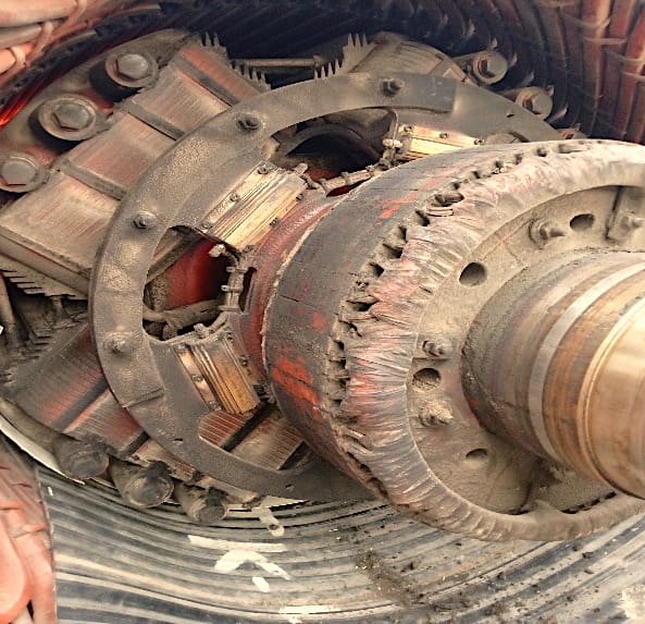
Those units with ventilation air fans forcing the air through the canopy might be pushing in the moisture and dust/dirt if the filters aren’t up to the mark or have aged well. If there are slits/openings in the end cover of the generator without any filtering sheet, the dust/dirt and fumes from the breather enter directly inside the generator and come in direct contact with the stator and field windings.
In brushless excitation systems, where another exciter generator is mounted on the same shaft, its field and the armature windings are also exposed to the same environment.
Figure 8 – Slits/Opening Design for Air Inlet
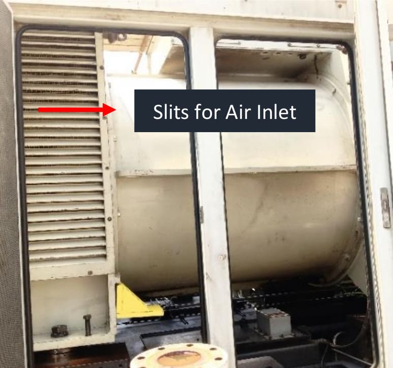

Figure 9 – A Highly Carbonized Rotor

Insulation Resistance Acceptable Criteria:
Field winding of a generator is a low voltage winding and hence not tested normally above 500 V for insulation resistance. There are different versions of minimum acceptable value of IR test for AC and DC armature and field windings.
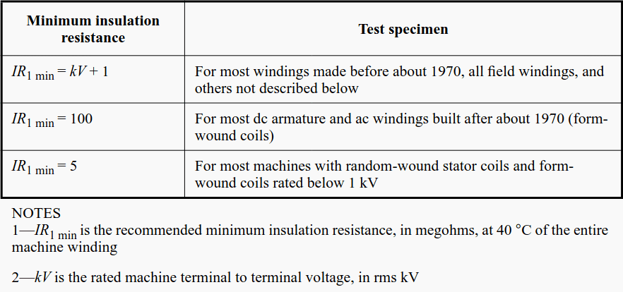
IEEE Std 43 recommends below formula for the minimum acceptable value of insulation resistance,
Rm = kV + 1
Where:
- Rm = recommended minimum insulation resistance in megaohms
- kV = rated machine terminal to terminal voltage
Following table from IEEE Std guides further on the insulation resistance values.
Table 1 – Recommended minimum insulation resistance values at 40 °C

Testing Approach:
Insulation resistance test is the only major test performed on field winding by the utilities apart from Recurrent Surge Oscillograph (RSO) performed to detect turn-to-turn shorting. So, one has to establish the belief on the winding integrity of the field around just one test.
There are three different kinds of tests that one can perform with an insulation tester as listed below:
- Short-Time or Spot-Reading Test
- Time-Resistance Test
- Step or Multi-Voltage Test
It is usually the short-time test that we are usually performing on the field winding of a generator in which it is tested for a very brief period of time and gives a spot reading and we simply map the obtained reading against the previous ones.
But there is a different approach followed with the time-resistance test in which the test voltage is applied for longer periods so that the capacitive charging current and the absorption current die out effectively and a higher leakage current could be detected if the reading isn’t improving as the duration of the test passes on. It is this concept that works behind the Dielectric Absorption Ratio (DAR) and Polarization Index (PI) test.
Related Study – Measurement of insulation resistance (IR)
Test at Voltages Slightly Higher
The final approach is to go for multi-voltage test in which the test voltage is raised above the operating voltage of the machine. When tested with usual voltage, the value of resistance may turn out to be normal, however, testing the asset at a slightly higher voltage may reveal an incipient weakness/spot that turns up at higher voltages only. Moisture and dirt in insulation are usually revealed by tests at voltages around those expected in service.
However, effects of aging or mechanical damage in fairly clean and dry insulation may not be revealed at such low stress.
This approach of increased test voltages for low voltage windings could be useful where the visual inspection does indicate signs of probable deterioration with the presence of carbonized dust on the windings for the reasons discussed in the section of causes of failure.
Figure 10 – Comparison Curves for Multi-Voltage Test
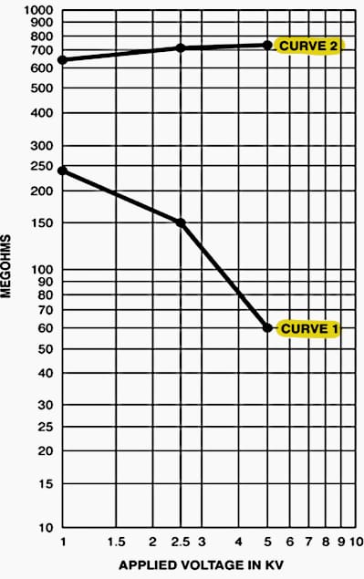

It can be seen from the two curves on the plot that for one system the readings only improved with stresses whereas for the system having weak spots was exposed as the test voltage was increased. This approach may be useful for the field winding as we don’t have too many options like the stator winding where can perform tan delta, PD, DAR and PI tests.
Protections Against Field Grounding Failure:
Two protections associated with any failure of the field windings will be discussed here:
- Field Ground Protection (64F)
- Loss of Excitation (40)
64F field ground protection detects the lowering insulation resistance and initiates an alarm or tripping as configured. Its working is based on injecting a dc or a low-frequency square wave with one reference being the main field winding while the other being the ground through the shaft earthing brush mainly.
The figure illustrates below the circuitry of a field ground relay on a brushless excitation system, where slip rings are mounted for the 64F circuit only.
Figure 11 – Connections for 64F through slip rings
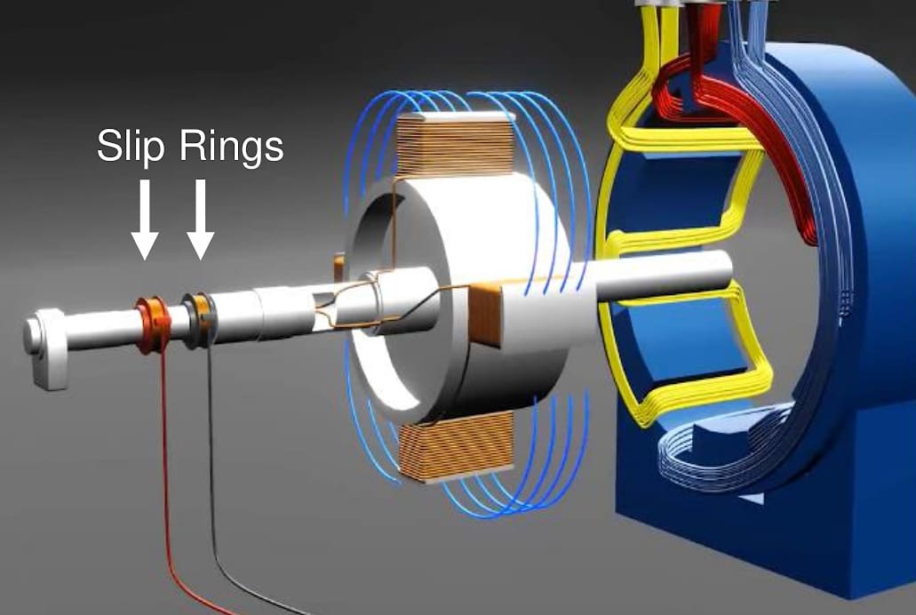

Figure 12 – Square Wave Injection Method
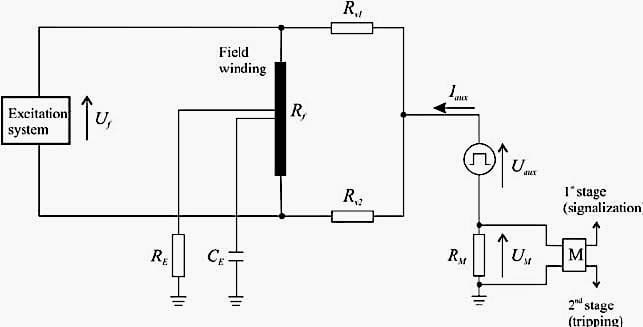

A square wave generator drives the current through the field winding whenever there is a field ground and the resulting current causes a voltage drop across the measuring resistor shown in Figure 12, which is measured directly by the relay.
The relay calculates the leakage current from the measuring resistor as:
I = Vm/Rm
Once the value of leakage current is obtained, the value of insulation resistance Rg is calculated as,
Vinj = I (Rc/2 + Rg + Rf + Rm)
Where,
- Rc = Coupling resistors
- Rg = Insulation resistance
- Rf = Field winding resistance
- Rm = Measuring resistor
Since the voltage used is AC for the relay detection, there remains the problem of capacitive leakage currents. For that matter, DC injection method is used,
Figure 13 – DC Injection Circuitry

Loss of Excitation:
Loss of excitation relay acts if the field circuit gets open circuited and is the only reliance should the field is shorted from two locations provided the unit is being operated by bypassing the field ground protection against single point ground. An offset mho relay is widely known with detecting the loss of excitation whenever the field winding is short circuited or open circuited.
It is an impedance-based method because the measured generator resistance will drop during loss of excitation conditions.
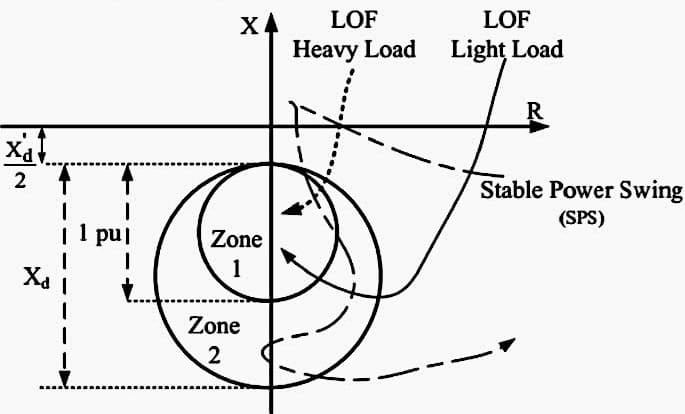
The final generator impedance after the loss of field depends on generator loading before the fault. If the generator was lightly loaded before the fault, the final impedance will be near the generator’s synchronous impedance (Xd). If the generator was heavily loaded before the occurrence of fault, the final impedance will be closer to the generator’s transient impedance (X’d).
R-X Diagram of Machine:
On R-X diagram, the relay characteristic is an offset circle with the offset equal to one half of the transient reactance (X’d). This offset is provided because the minimum expected impedance during loss of field being is close to the transient impedance (case of heavily loaded unit) and so this offset, being equal to one-half of the transient impedance, would ensure relay operation even if the calculations are slightly off.
The diameter of the mho circle will be equal to generator’s synchronous impedance because this is the maximum expected value of impedance during loss-of-field (case of lightly loaded generator). This solitary circle/zone covers for the loss of excitation on the generator operating from 0-100% of the rated load.
Further Study – 4 essential implementations of protective relays in power systems
4 essential implementations of protective relays in power systems
Additional Zone to Cover Nuisance Tripping:
But nuisance tripping has been observed against transitory power swings which push the positive sequence impedance of the machine into the relay zone. In order to counter that, an additional zone 2 is defined in the relay with the same offset as the zone 1 but diameter equal to the base impedance of the machine. This covers for the loss of excitation on a generator operating from 30-100% of the rated load prior to the fault.
The first zone now covers the lightly loaded scenarios (<30%) and its time delay is increased so that a momentary power swing is passed safely without any nuisance tripping.
Figure 13 – Mho Circle Characteristics

Conclusion:
The associated circuitry of the field windings should also be inspected and tested when opportunity arrives. Failures could happen due to the exciter generator field and armature winding or rotating rectifiers in brushless excitation systems.
Similarly, hidden weakness in the field winding could go undetected when tested with normal voltages because Insulation Resistance (IR) is probably the only test that utilities are performing on the field winding of a generator mostly unlike the PD, tan delta, PI and DAR that paint a comprehensive picture of stator winding.
Suggested Course – Generator Protection Course: Concepts, Applications and Relay Protection Schemes
Generator Protection Course: Concepts, Applications and Relay Protection Schemes


Sooper bro👍