Differential current
Certain phenomena can cause a substantial differential current to flow, when there is no fault, and these differential currents are generally sufficient to cause a percentage differential relay to trip.


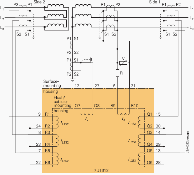
However, in these situations, the differential protection should not disconnect the system because it is not a transformer internal fault.
Such phenomena can be due to the non-linearities in the transformer core. Some of these situations are considered below //
1. Inrush currents
Magnetizing inrush current in transformers results from any abrupt change of the magnetizing voltage. Although usually considered as a result of energizing a transformer, the magnetizing inrush may be also caused by //
- Occurrence of an external fault
- Voltage recovery after clearing an external fault
- Change of the character of a fault (for example when a phase-to-ground fault evolves into a phase-to-phase-to-ground fault)
- Out-of-phase synchronizing of a connected generator
An example of inrush current following a reclose operation measured at the distribution substation breaker.


Since the magnetizing branch representing the core appears as a shunt element in the transformer equivalent circuit, the magnetizing current upsets the balance between the currents at the transformer terminals, and is therefore experienced by the differential relay as a “false” differential current.
The following summarizes the main characteristics of inrush currents //
- Generally contain DC offset, odd harmonics, and even harmonics.
- Typically composed of unipolar or bipolar pulses, separated by intervals of very low current values.
- Peak values of unipolar inrush current pulses decrease very slowly.
- Time constant is typically much greater than that of the exponentially decaying dc offset of fault currents.
- Second-harmonic content starts with a low value and increases as the inrush current decreases.
Read more about practical considerations of transformer inrush current //
2. Overexcitation conditions
Overexcitation of a transformer could cause unnecessary operation of transformer differential relays. This situation may occur in generating plants when a unit-connected generator is separated while exporting VARs. The resulting sudden voltage rise impressed on the unit transformer windings from the loss of VAR load can cause a higher than nominal volts per hertz condition and, therefore, an overexcitation event.
This could also occur in transmission systems where large reactive load is tripped from a transformer with the primary winding remaining energized.
When the primary winding of a transformer is overexcited and driven into saturation, more power appears to be flowing into the primary of the transformer than is flowing out of the secondary. A differential relay, with its inputs supplied by properly selected CTs to accommodate ratio and phase shift, will perceive this as a current differential between the primary and secondary windings and, therefore, will operate.
Since overexcitation manifests itself with the production of odd harmonics, and since the third harmonic (and other triples) may be effectively cancelled in Δ transformer windings, then, the fifth harmonic can be used as a restraining or a blocking quantity in the differential relay in order to discriminate between the over-excitation and the faulty state.

3. Current transformer saturation
The effect of CT saturation on transformer differential protection is double-edged. Although, the percentage restraint reduce the effect of the unbalanced differential current, in the case of an external faults, the resulting differential current which may be of very high magnitude can lead to a relay male-operation!
For internal faults, the harmonics resulting from CT saturation could delay the operation of differential relays having harmonic restraint.
Reference // Transformer Differential Protection Scheme With Internal Faults Detection Algorithm Using Second Harmonics Restrain And Fifth Harmonics Blocking Logic – Ouahdi Dris, Farag. M. Elmareimi and Rekina Fouad




I have a ( 33Kv to 11K Sub) problem 33kv Trf diff relay, every time when I have fault down stream of the network, the Trf diff always trip first on the faults that are out of it’s zone “” I mean it’s jumps my incomer relay as well as my outgoing feeder really. Please advise.
I found a strange problem with differential relay installed for Generator, Transformer, operating when there were no grid fault in the associated network at the time of trip. Even though this was a nightmare for operation and maintenance engineers for more than five years as the relay and current transformer wiring, insulation between cores, pick up value and stable for through fault injection and bias characteristic was also as per graph. When I analyzed for 3 days I found that the trip contact wires were normal telephone wires with low voltage rating probably meant for 48 volts DC and these wires punctured due to the high voltage station DC 220 volts and float voltage was 231 volts (+5%) and this 231 V is constantly applied between trip relay output contacts and it is when the insulation between twisted wires collapsed it created short circuited positive supply to the associated trip circuit without any relay operation. After the flash over between trip wires insulation gets punctured and open again. I have done more than 300 tests and finally on 3rd day I was lucky to notice a spark and puncture. Later Teflon sleeved were provided in all the relays installed in India. No wrong trip after this modification. If a relay trips at least 1 or 1.5 kV to be applied across the output relay contacts to confirm there is no partial leakage. Remember 2 kV 50 Hz 1 minute insulation is required between trip wires across contact. Add this while investigation cause of mis operation of any relay 9840229620
At switchyard 33KV line-1 Y-phase LA got burst and transformer-1 got tripped on differential protection and Bucchholz’s protection. After replacement of LA ,while charging the transformer-1 it is tripping in Differential protection two times.We had carried out ratio test ,found ratio value is uniform.IR and PI value of transformer is good i.e coming in Giga ohm .Still it is tripping in diff.protection.Suggest if any testing is required for healthiness checking of the transformer ,also mention the name of the tests to be carried out.
While charging under No load transformer tripped due to Differential Protection in R Phase internal inspection done and proper processing done and LV Test conducted including DGA Results, everything is ok, after charging immediately tripped due to Differential in same phase, what could be the reason , how to check the sub station protections its new sub station pl guide
Dear
We are mfg.CTs, PTs (Current & Potential Transformer) & Metering Cubicle/Unit upto 33KV system voltage OIL , DRY TYPE CT s. , PTs. 11KV UPOT 440KV, L.T .HT METERING CUBICLE & CT-PT UNIT, VCB SF6 66 OCB SFU RMU 220KV SF6 OIL & DRY TYPE POWER & DISTRIBUTION & CONTROL TRANSFORMERS, SALVO STABLIZER ,415V UPOT 440KV 1KVA UPOT 100MVA , LIGHTNING ARRESTORS ,ISOLATATORS RELAY CONTROL PANEL,CABLES LT, HT UPOT 33KV , CABLES JOINTING KITS GO/DO INSULATORS SILENT DG SATE ALL ELECTRICAL SPAIR If you have any requirement, please mail : us, we will offer our most reasonable price and best
quality
We need transmission materials almost everything
I feel so thakfull for your efforte of making thing close and clear hope you more better future and happy times