
Estimated Study Time: 16 minutes
Effective impedance under fault
The analysis of faults in the synchronous machine and transformer windings presents a special difficulty because the effective impedances of the affected windings under internal fault conditions are not normally known. The methods of analysis are severely limited and are usually concerned with obtaining a reasonable estimate based on certain simplifying assumptions.
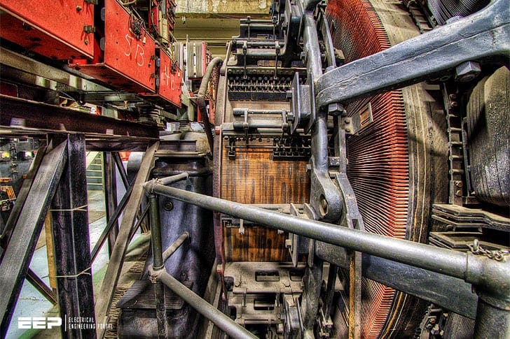 Analysis of faults in machine and transformer windings (on photo: Located at the deepest in NYC, these generators powered the NYC railroad system During WW2 they were guarded from German soldiers; credit: Wasabi Bob via Flickr)
A particular case in which simplifying assumptions can yield quite accurate results is that concerned with the analysis of earth faults on impedance-earthed windings, where the neutral-earthing impedance can be regarded as large compared with the winding impedance.
1. Generator-winding faults
Consider the generator shown in Figure 1 and let it be assumed that a short-circuit condition occurs at the point F, a per-unit distance x from the generator neutral point.

Let it be further assumed that the generated e.m.f, (phase-a value) in that portion of the winding between the neutral point and the point of fault is xE, where E is the value appropriate to the full winding, the e.m.f, in the remaining portion of the winding thus being (1 – x)E.
It follows, therefore, that the positive, negative and zero-sequence circuits of the generator will have the form shown in Figure 2 below.
It will be noted that there are now three generator impedance values to be considered for each of the three phase-sequence circuits, namely ZN, ZL and ZF, respectively, with appropriate phase-sequence suffixes, the values of these impedances depending on the fault position x and the normal full-winding values of the generator phase-sequence impedances Z1, Z2 and Z0.

In order to apply the generator phase-sequence circuits of Figure 2 it is, of course, necessary to determine the required impedance values, given the values of x, Z1, Z2 and Z0,
Some assumption must, therefore, be made to obtain these values and the simplest of these is to assume that:
- there is no mutual coupling between the neutral-to-fault and fault-to-line sections of the winding, and
- that the impedances appropriate to each of these two winding sections are proportional to lengths of these sections.
The phase-sequence circuits which result from these assumptions are shown in Figure 3, from which it will be seen that:
the remaining impedances ZF1 , ZF2 and ZF0 all being zero.
Hence, considering a three-phase fault at F, the resultant fault current value is given by:
the value of the fault current thus being seen to be independent of fault position. Similarly, for a phase-to-phase fault at F, the value of the phase-fault current is given by:

which is also seen to be independent of the fault position. Considering now, a single-phase-to-earth fault at F, the value of the fault current is given by:
and if Zn is very much greater than Z1, Z2 and Z0, the expression for the fault current reduces to the approximate form:
It is being further assumed that the short-circuit current If is quite independent of the position of the short-circuited turns within the winding.

With these assumptions, the value of the fault current will be precisely the same as for a phase-to-neutral fault at a per-unit distance x from the neutral point, the fault current being therefore given by:
The value of the fault current is thus seen to be independent of the fraction of the winding spanned by the short-circuit.
In all the above-mentioned fault conditions, the effect of fault infeed from the generator terminals can be taken into account by connecting the generator phase-sequence circuits of Figure 3 to those applicable to the rest of the system.
It should be noted also that this simple treatment is applicable only to the case of a generator with a single-conductor stator winding.
A more rigorous treatment, applicable to generators with stator windings having a number of paths in parallel, is given by V.A. Kinitsky in his work “Calculations of internal fault currents in synchronous machines”.
1.1 Interturn faults detection methods
A generator is often wound with a double-layer, multi-turn winding. The generator winding may be a single circuit or there may be 2, 4, 6 or 8 branches in parallel. Under normal operation there is very little difference in the current in each branch.
However, during an internal fault, currents will circulate between the parallel branches of the winding within one phase. Split phase protection takes advantage of this characteristic by measuring the current unbalance between these parallel branches. In hydro machines a significant percentage of stator faults begin as turn-to-turn faults.
These faults are not detectable by the stator differential or ground fault protections since there is no difference between the currents at the output and the neutral terminals and there is no path for fault current to ground. If these faults can be detected before they evolve in to phase or ground faults then the damage to the machine and associated downtime can be greatly reduced.
Therefore the split phase protection should ideally be sensitive enough to operate for a single-turn fault in the winding of the machine.
There are several methods currently in use today:
1.1.1 Scheme A
In scheme A, a neutral point is brought out for each parallel circuit. An overcurrent element is connected between each neutral. During an inter-turn fault, a circulating current is produced in the faulted phase that is passed between the neutrals.
1.1.2 Scheme B
In this scheme a differential and restraint signal are derived using currents from both sides of the machine. One current represents the total current in the machine while the other is the current from a CT representing 1/2 the total current.
This scheme is also known as “combined split phase and differential” or “partial longitudinal differential”.

1.1.3 Scheme C
In scheme C, the currents from each parallel circuit are used to derive a differential and restraint signal. The relay has a percent slope characteristic.
This scheme is sometimes known as “transverse differential”.
1.1.4 Scheme D
The scheme shown in Figure 4 also responds to the difference between the currents in the two circuits. However, the summation is done outside the relay. Therefore this method cannot derive a restraint signal.
As such this scheme usually employs a definite time or inverse time characteristic for security.

1.1.5 Scheme E
In this scheme a window-type CT is used to measure the difference between the current in each circuit, as shown in Figure 9.
This method avoids the CT error issues of Scheme D.

2. Transformer-winding faults
In dealing with earth faults on transformer windings, the special case of impedance-earthed windings is amenable to the simplified treatment already described in the above section, the value of the fault current being the pre-fault phase-to-earth voltage at the point of fault divided by the effective value of the system earthing impedance.
The two cases of most common interest are shown in Figures 10 and 11, namely the star-connected winding and the delta-connected winding.

It is of interest to note, in the case of the delta-connected winding, that the pre-fault phase-to-earth voltage has a minimum value when the fault is at the centre of the affected winding, this minimum value being one half the phase-to-neutral voltage.
From the cosine rule above, we get:
- Ef2 = E2 + (x√3E)2 – 2x√3E2 cos30°
- giving: Ef = E√(1 + 3x(x-1))
- where: x = bF/bc
As will be seen from above Figure 12, the magnitude of the pre-fault phase-to-neutral voltage Ef, at the point of fault is:
![]()
where:
- E is the phase-to-neutral voltage of the winding and
- x is the per unit distance of the fault from one terminal of the winding.
The case of an earth fault on a solidly-earthed star-connected transformer winding is of particular interest, and has been investigated by tests on a 132/33 kV 45 MVA star/delta transformer, the results being as shown in Figure 13.
Notes
It will be noted that, within the limited range of fault positions investigated (accessible by virtue of the tap-change connections), the earth-fault current is a maximum for a fault close to the neutral point, the current flowing into the winding from the phase terminal having a minimum value of zero for a fault in this position.
Transformer earth fault protection (VIDEO)
This video shows the key elements of transformer earth fault protection.
Sources:
- Power system protection; Principles and component
- Self-Adaptive Generator Protection Methods by D. Finney, B. Kasztenny, M. McClure, G. Brunello – General Electric and A. LaCroix – Hydro Québec
Related electrical guides & articles


Edvard Csanyi
Hi, I'm an electrical engineer, programmer and founder of EEP - Electrical Engineering Portal. I worked twelve years at Schneider Electric in the position of technical support for low- and medium-voltage projects and the design of busbar trunking systems.I'm highly specialized in the design of LV/MV switchgear and low-voltage, high-power busbar trunking (<6300A) in substations, commercial buildings and industry facilities. I'm also a professional in AutoCAD programming.
Profile: Edvard Csanyi

thanks so much
It’s very gud knowledge about electrical field and medium voltage
sir i need help in multi level inverter becuase it is my final year project . can u send me report about multi level inverter