
Estimated Study Time: 15 minutes
Condition monitoring
Condition monitoring equipment that can be used to extend the life of a transformer or to prevent catastrophic failure could pay for itself many times over. However, condition monitoring does not come free of charge, and tight budgets are to be met.
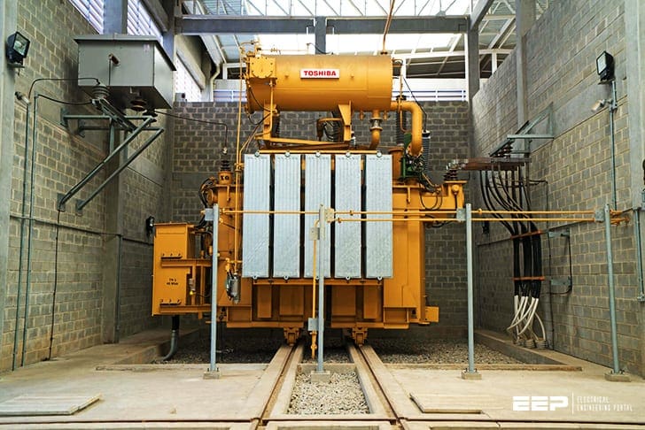 How do faults develop in a HV transformer and why condition monitoring is important
Life-cycle costing must be applied. This comes from the summation of the installation, maintenance, repair and operation costs. Several options of monitoring equipment covering a wide spectrum of cost are available or are in development.
Monitoring equipment looking at one or two specific parameters is readily available on the market at relatively low cost. At the other end of the cost spectrum, not only can many parameters be monitored, but also an expert system or artificial intelligence capable of generating an estimate of the overall plant condition will interrogate the data.
A single monitor costing a relatively small sum of, say, £2000, if fitted to every transformer on the NGC system, would give a total cost of more than £1 million. To this expense is added the cost of a communication system to bring the data to a central location. Additionally there is the cost of maintaining the monitoring system itself.
Just as in the domestic insurance market, where many insurance companies will reduce household contents premiums if security devices and alarms are fitted to domestic property, it surely cannot be too long before electrical equipment will be uninsurable unless condition monitoring is applied.
Which parameters should be monitored?
Each utility has a unique view on which parameters should be monitored. A utility that has experience of a dominant failure type on its transformers or has a family of transformers which demonstrates a particular failure type is likely to want to monitor more parameters relating to that failure than a utility whose prime objective is to reduce maintenance costs.
Some parameters, especially those intended to show fast or medium rate fault development, will require on-line monitoring, while others are more economically handled by regular inspection. Each utility must make its own selection of the most appropriate monitoring system.
There is no universal solution.
How do faults develop?
Faults in transformers can develop extremely quickly, in the space of seconds, milliseconds or even nanoseconds. In such circumstances, the principal aim is to reduce the degree of damage to the faulted equipment and protect the remainder of the system from the effects of the failure.
Other faults may develop within periods measured in minutes, hours or days.
The aim, then, is to prevent catastrophic failure and perhaps even to extend the life of the plant by controlled usage or to achieve a planned isolation of the faulty plant with the minimum of system disruption.
Finally, there are faults that take weeks, months and sometimes years to evolve, permitting planned refurbishment or replacement.
Continuous or period monitoring?
In-service monitoring is sometimes possible on a continuous basis or by periodic checking and trend identification. Periodic checking, furthermore, may require de-energisation of the transformer, and possibly disconnection from the system. Each utility will consider the costs and the value in the decision on what should be monitored.
Intrusive measurements are also an extreme possibility, but would generally only be adopted after one or more continuous or periodic monitors identify a potential problem.
What transformer parameters can be monitored?
Internal and external sensors can be used to support in-service monitoring, but additional data or measurements related to loading provide further information on which assessments of condition are made.
Monitors available in the market place are capable of monitoring such parameters as partial discharge, temperature, dissolved gas in oil, fur-furans, moisture, resistance, capacitance, frequency response analysis, polarisation spectrum, mechanical position and current.
- Partial discharge monitoring
- Temperature
- Chemical parameters
- Dielectric parameters
- Bushing and tap-changer monitoring
1. Partial discharge monitoring
Dielectric breakdowns in transformers are most frequently preceded by partial discharges, i.e. a partial breakdown across a part of the insulation structure. Since partial discharge often occurs before a complete breakdown, partial discharge monitoring can provide a warning of future and perhaps catastrophic failure. Not all partial discharges, however, are potentially damaging in the short term.
For example, loose connections, floating metallic objects arcing under oil between metal parts, may not be of immediate concern, but monitoring with a view to eventual correction could save money in the longer term.
Partial discharges can be successfully detected by electrical methods, for example using RIV or a Lemke probe. Other more sophisticated equipment that analyses the discharge signals by magnitude, by position and polarity with respect to the voltage wave and compares with a known signature pattern is available or under development.
In this respect the author’s own company (Alstom) has developed sophisticated equipment and is about to build more units for operational experience before putting them on the open market.
One highly regarded method for the detection and location of partial discharges uses acoustic sensors. Partial discharges generate sound waves in the 100 to 300 kHz ranges. This sound is at a much higher frequency than the background noise of the transformer, and allows discrimination of the signals. In addition, sound takes a finite, measurable time to travel from source to monitor.
The source of a partial discharge can often be located by triangulation from an array of sensors at several positions around the transformer tank.
2. Temperature
Temperature measurement also provides a good indication of the condition of the transformer. Infrared photography is a fully tried and tested means of measurement of external features on a transformer, such as bushings, bushing connectors and tank surfaces.
Equipment and operators are hireable on half-day or day rates.
Direct oil temperature measurement is a relatively easy process. Temperature measurement elsewhere in the transformer is much more difficult to perform. Most oil-immersed transformers are fitted with analogue devices since direct measurement has historically produced increased dielectric risk. Fibre optic techniques have dramatically reduced this risk.
The lack of splicing techniques and the unavailability of suitable mechanical protection (demanded by use with procedures applied to heavy equipment production and drying processes) renders them unproven at present.
3. Chemical parameters
The first indication of faults inside oil filled transformers is usually obtained from the gases dissolved in the oil. Oil and cellulose insulation materials degrade under thermal and electrical stresses, and in doing so generate gases in various compositions and concentrations.
Regular oil sampling and analysis of the hydrocarbon and carbon oxide gases in the sample are probably the most cost-effective methods of condition monitoring. Sample analysis will identify the longer-term fault development. Some other trigger can identify faults developing in days or months.
Devices such as the Hydran Gas Monitor, which provide an alarm when the gas concentration reaches a pre-set level, can be used to initiate a more rigorous and more frequent condition-checking process. On-line chromatography is also available at a price.
High performance liquid chromatography can be used in the measurement of the furfuraldehyde content of the oil, giving an indication of the micro-deterioration of the transformer and therefore the true age of the cellulose insulation.
4. Dielectric parameters
Frequency response analysis, recovery voltage spectrum and dielectric loss angle are becoming more accepted among utilities throughout the world, but there still remains polarisation of opinion and a need to exchange information and experiences in order to reach agreed philosophies and procedures, particularly in relation to the recovery voltage method.
5. Bushing und tap-changer monitoring
A CIGRE questionnaire on transformer failures was analysed and reported by Bossi et al. in 1983. This report identified the relative numbers of components involved in transformer failures. Some of the CIGRE Report findings identify the principal components involved in transformer failure and are reproduced as Table 1 below.
It is significant that on-load tap-changers and bushings figure prominently in the table.
As for the transformer, partial discharge monitoring techniques are relevant to the dielectric condition of the tap-changer. The mechanical and thermal condition determination requires detection of relative mechanism discrepancies, confirmation of diverter timing and selector/diverter sequencer and measurement of current through the transition resistor.
Various devices, some with fibre optic links for greater reliability, are available in the marketplace.
Insulation systems of condenser bushings and high voltage current transformers generally consist of alternating layers of metallic foils and oil-impregnated paper. A small capacitive charging current flows continuously when the system is energised.
An electrical breakdown of the insulating layers leaves carbon deposits that may short-circuit adjacent foils. The capacitance of the system is reduced and the charging current increases. A current probe is available in the USA that plugs into the capacitive tap of the bushing. it is claimed that this device may be installed within centimetres of high current leads, without denigration of its reliability.
Conclusions
Significant inroads into condition monitoring philosophies, equipment and systems have been made in the past few years. The speed of progress has been driven by the need to make the best possible use of existing and new equipment to give reliable and long service. Transformers constitute one of the most reliable sectors of electrical plant. However, we cannot afford to be complacent.
There is still much to be done in the condition monitoring arena – equipment to be developed, philosophies to be debated and procedures to be agreed.
Table 1 – Components causing failure of transformers in service
| Windings | 29% |
| Terminals | 29% |
| Tank and fluid | 13% |
| On-load tap-changer | 13% |
| Magnetic circuit | 11% |
| Other accessories | 5% |
In addition, consideration must be given to the integration of all substation monitoring with modular add- on capability to provide complete system packages. Our dreams will eventually become reality.
Reference // Condition and monitoring of HV equipment by A.White
Related electrical guides & articles


Edvard Csanyi
Hi, I'm an electrical engineer, programmer and founder of EEP - Electrical Engineering Portal. I worked twelve years at Schneider Electric in the position of technical support for low- and medium-voltage projects and the design of busbar trunking systems.I'm highly specialized in the design of LV/MV switchgear and low-voltage, high-power busbar trunking (<6300A) in substations, commercial buildings and industry facilities. I'm also a professional in AutoCAD programming.
Profile: Edvard Csanyi

What are the causes related to earthquakes? Where an earthquake of magnitude 5.5 occurred, when the earthquake occurred, the transformer was disconnected and the monitoring devices gave a malfunction (Buchholz Trip), what is your explanation for this type with your experience, and thank you very much .
Dear Sir-Edvard Csanyi,
Will you please give a write up mentioning that use of a 3 GAS Online DGA (Moisture, H2 & CO) is basic requirement to save the transformer from complete damage.
Thanks & Regards,
Abdul Jalil
Great article Edvard! I am with a startup (Tagup) in Boston that is utilizing advanced machine learning algorithms and AI developed out of MIT to prevent unplanned failure of power transformers using DGA and other equipment data. Feel free to get in touch to discuss further.
Very important in the field of engineering