
Estimated Study Time: 7 minutes
Earthing in a high leakage current environment
Most modern electronic equipment uses switched mode power supplies (SMPS) which draw pulses of current from the mains supply rather than a continuous sinusoidal current.
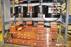
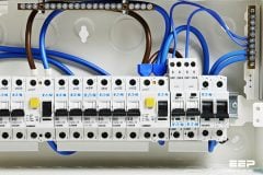
 Few Advice For Improving Integrity Of Protective Conductor (photo credit: electric.answers.com)
The fast rise time edges of the current waveform contain high frequencies that can cause serious radio frequency interference (RFI) to other equipment in the vicinity. To prevent propagation of this interference on to the supply each SMPS incorporates a filter on the input consisting of a small series inductor in both the phase and neutral lines with a small capacitor to ‘earth’ from each.
Since the filter capacitor provides a path from phase to the protective conductor, current will flow. This current is made up of a small current (permitted by regulation to be up to 3.5 mA) at the fundamental frequency, a small fraction of each harmonic frequency present and high frequency transients caused by switching.
Typically each desk will have at least a personal computer and monitor, each contributing to the leakage current. This amounts to a change of function for the protective conductor system; while it used to be provided only to carry current in the event of a fault it is now required to carry a continuous leakage current as well as serving as a sink for high frequency noise currents.
Now that the protective conductor has both safety and functional requirements to fulfil, the designer must take many more factors into consideration during design, and the services manager must be vigilant to ensure safe use. For example – integrity – to ensure the safety of operators and the public.
Leakage current //
Since the protective conductor is now carrying a leakage current, any break in the ‘earth’ side connection to it will mean that the isolated section will rise to a potentially lethal voltage – half of the supply voltage – as will all the exposed metalwork connected to it. The current available to flow will depend on the total leakage current of the equipment connected to that section.
European wiring regulation standard IEC 7671 (and BS 7671) attempts to improve the integrity of such circuits by requiring that a final circuit in which the leakage current is expected to exceed 10 mA must meet either of the following two requirements:
1. Following one of the methods below //
A high integrity earth must be provided by one of the following methods:
- A single protective conductor with a cross-sectional area of not less than 10 mm2.
- Separate duplicate protective conductors with a cross-sectional area of not less than 4 mm2, independently connected.
- Duplicate protective conductors incorporated in a multi-core cable with the live conductors of the circuit if the total cross sectional area of all the conductors is not less than 10 mm2. One of the conductors may be formed by metallic armour, sheath or braid incorporated in the construction of the cable.
- Duplicate protective conductors formed by conduit, trunking or ducting and a conductor having a cross-sectional area of not less than 2.5 mm2 installed in the same enclosureand connected in parallel with it.
- An earth monitoring device which, in the event of a discontinuity in the protective conductor, automatically disconnects the supply of the equipment.
- Connection via a double wound transformer where the input and output circuits are electrically separated. The protective conductor between the equipment and the isolating device must be provided by one of the methods (point 1 to 5. above).
2. Ring connecting single sockets
The final circuit must be a ring connecting single socket-outlets with no spurs.
Each end of the protective conductor ring must be individually terminated (i.e. separate connections, individually screw clamped) to the distribution board.
One serious problem is that these regulations apply to final circuits in which the leakage current is expected to exceed 10 mA. Often, the use of the circuit is not known to the installer, and indeed changes over the lifetime of the building, so the above requirements are not implemented.
This means that many circuits do not have the required protective conductor integrity to safely supply IT and other electronic equipment.
Continuity Test of Protective Conductors (VIDEO)
Reference // A Good Practice Guide to Electrical Design – Copper Development Association (Download guide)
Related electrical guides & articles


Edvard Csanyi
Hi, I'm an electrical engineer, programmer and founder of EEP - Electrical Engineering Portal. I worked twelve years at Schneider Electric in the position of technical support for low- and medium-voltage projects and the design of busbar trunking systems.I'm highly specialized in the design of LV/MV switchgear and low-voltage, high-power busbar trunking (<6300A) in substations, commercial buildings and industry facilities. I'm also a professional in AutoCAD programming.
Profile: Edvard Csanyi

Dear Sirs, Greetings.
Usually , in Practice, half the size of the power cable conducter is used as a protective conducter as protective conducter.
Is this correct as per the Norms? per Specs? Please guide.
Warmest regds.
Hi, this practical reduction of diameter of neutral or grounding cables is done to reduce cost – technically it is the worst thing you can do. the reduction of the diameter leads to overheating of the cable and later on to electrical fire. remember – 60W can create fire !!
Residual current monitors from BENDER (RCMA (single channel) / RCMS (multi channel)) can tell you ahead of time when such a situation occurs and can shut down the circuit if needed.
Check our homepage in India:
Bender India Private Limited
805, B-Wing, 8th Floor
TECHNOCITY, Plot No X-4/1 & X-4/2
MIDC, TTC Industrial Area
Mahape, NaviMumbai – 400710
Maharashtra, INDIA
Contact: Mr. P. K. Bhattacharyya
Phone: +91-22-27788501
Phone: +91-22-27788502
Fax: +91-22-27788503
E-Mail: [email protected]
Web: http://www.bender-in.com
Thank your share.
we just produce the electronic parts,what’s the best way for sale?thank you.