
Duration diagram //
To help estimate pumping energy costs:
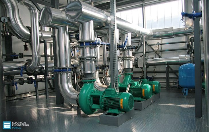 Estimating Pumping Energy Costs (photo credit: rightenergysolutions.com.au)
To compare different system and pumping equipment proposals and make an intelligent choice, three facts will need to be established:
- Will the process require varying flow rate, and, if so, must it be continuously variable or can flow rate be varied in steps?
- Can on-off batch pumping be used?
- What is the peak flow rate and how is the flow rate distributed over time?
The answers to these questions will determine if, and how, to regulate the flow. It will also give some guidance regarding the pumping system design. A helpful way of showing the flow demand is to use a duration diagram.
A duration diagram in its simplest form (see Figure 1) shows how many hours during a year that a given flow rate is needed – the dashed line. The solid curve in the same diagram is interpreted differently. Each point on the solid curve tells how many hours during a year the flow rate exceeds the value on the y-axis.
Use a duration diagram to help estimate pumping energy costs. This diagram is instrumental in understanding the pumping needs. The system must be able to deliver the peak flow, but, from an economic point of view, it is also important to know at what flow rates the system is going to operate most of the time.
To find the total cost of operating the pump, the running cost at each operating condition must be calculated and summated.
Capital Cost Savings //
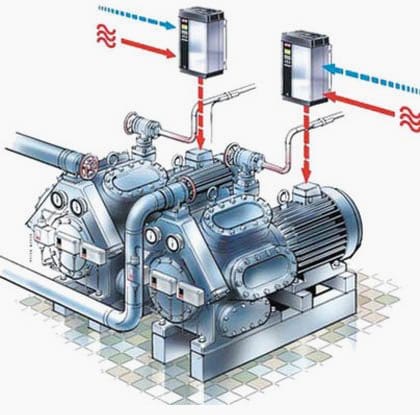
Variable Speed Drive
When designing and installing a new pumping system, the capital cost of a Variable Speed Drive (VSD) can often be offset by eliminating control valves, bypass lines, and conventional starters, as explained below.
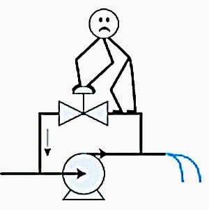
Elimination of Control Valves
Control valves are used to adjust rotodynamic pump output to suit varying system requirements. Usually a constant-speed pump is pumping against a control valve, which is partially closed for most of the time. Even at maximum flow conditions, a control valve is normally designed to be 10% shut, for control purposes.
Hence, a considerable frictional resistance is applied. Energy is therefore wasted overcoming the added frictional loss through the valve. Using a VSD to control flow can eliminate the control valve.
Elimination of Bypass Lines
All fixed-speed centrifugal pumps have a minimum flow requirement. If the pump is operated at flow rates below the minimum for extended periods, various mechanical problems can occur. If the flow requirements in a system can drop below this minimum flow capacity, it is necessary to install a constant or switched bypass to protect the pump.
The use of a Variable Speed Drive (VSD) greatly reduces the volume to be bypassed.
Financial Justification //
The initial cost of pumping equipment is often a very small part of the total life cycle cost (LCC). An LCC analysis is therefore a very appropriate way to compare different technical alternatives in the design of a pumping system and make a financial justification.
The components of an LCC analysis typically include(see Figure 2):
- Initial costs,
- Installation and commissioning costs,
- Energy costs,
- Operation costs,
- Maintenance and repair costs,
- Downtime costs,
- Environmental costs, and
- Decommissioning and disposal costs .
An LCC analysis is a very appropriate way to compare technical alternatives in pump system design to make a financial justification. The LCC equation can be stated as:
LCC = Cic + Cin + Ce + Co + Cm + Cs + Cenv +Cd
Where:
- C = cost element
- ic = initial cost, purchase price (pump, system, pipes, auxiliaries)
- in = installation and commissioning
- e = energy costs
- o = operating cost (labor cost of normal system supervision)
- m = maintenance cost (parts, man-hours)
- s = downtime, loss of production
- env = environmental costs
- d = decommissioning
Pumping up Energy and Water Savings with a VSD
Big Bertha, one of the largest line-shaft turbine and irrigation pumps in central Oregon, is saving watts and water after a recent facelift. The Van Akens and Grossmans used incentives from Bonneville Power and Central Electric Cooperative to upgrade Big Bertha with a variable speed drive, which allows them to better manage the watering requirements for the various crops on their 530 acres in Terrebonne, Ore.
A VSD is just one way you can save energy and water on your farm.
Reference // Variable Speed Pumping // A Guide To Successful Applications – Hydraulic Institute, Europump, and U.S. Department of Energy’s (DOE) Industrial Technologies Program


R/s :
Introduction : Age :64 , retired employee of BSNL – telecom co of Govt. of India , do few assignments as electrical engineer .Doing online course of IIT Madras.
2. Problem : a) I am still not clear about circuit analysis involving Dependable sources
b) How to determine negative feedback Opamp
3. Please help.
Regards