
Estimated Study Time: 7 minutes
Introduction to Synchronous Machine
There are two main types of synchronous machine: cylindrical rotor and salient pole. In general, the former is confined to 2 and 4 pole turbine generators, while salient pole types are built with 4 poles upwards and include most classes of duty.
Both classes of machine are similar in so far that each has a stator carrying a three-phase winding distributed over its inner periphery.
Within the stator bore is carried the rotor which is magnetised by a winding carrying d.c. current.
The cylindrical rotor type has a uniformly cylindrical rotor that carries its excitation winding distributed over a number of slots around its periphery. This construction is unsuited to multi-polar machines but it is very sound mechanically.
Hence it is particularly well adapted for the highest speed electrical machines and is universally employed for two pole units, plus some four pole units.
The salient pole type has poles that are physically separate, each carrying a concentrated excitation winding. This type of construction is in many ways complementary to that of the cylindrical rotor and is employed in machines having 4 poles or more. Except in special cases its use is exclusive in machines having more than 6 poles.
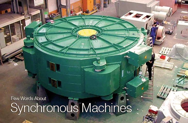
Figure 1 above illustrates a gearless synchronous generator for wind power plants developed by SIEMENS installed in a power plant. The unit, which has an extremely high efficiency rating of 98%, uses permanent magnets to convert wind energy from the rotor into electricity. The gearless generator avoids losses due to friction and heat and starts to operate even at low winds or in brief gusts. Because of this innovative design the generator doesn’t need gear oil and has fewer mechanical parts subject to wear and tear, which means less downtime.
Two and four pole generators are most often used in applications where steam or gas turbines are used as the driver. This is because the steam turbine tends to be suited to high rotational speeds.
Four pole steam turbine generators are most often found in nuclear power stations as the relative wetness of the steam makes the high rotational speed of a two-pole design unsuitable.


Most generators with gas turbine drivers are four pole machines to obtain enhanced mechanical strength in the rotor- since a gearbox is often used to couple the power turbine to the generator, the choice of synchronous speed of the generator is not subject to the same constraints as with steam turbines.
Generators with diesel engine drivers are invariably of four or more pole design, to match the running speed of the driver without using a gearbox. Four-stroke diesel engines usually have a higher running speed than two-stroke engines, so generators having four or six poles are most common.
This requires a generator with a large number of poles (48 for a 125rpm, 50Hz generator) and consequently is of large diameter and short axial length. This is a contrast to turbine-driven machines that are of small diameter and long axial length.
Armature Reaction
Armature reaction has the greatest effect on the operation of a synchronous machine with respect both to the load angle at which it operates and to the amount of excitation that it needs.

The phenomenon is most easily explained by considering a simplified ideal generator with full pitch winding operating at unity p.f., zero lag p.f. and zero lead p.f. When operating at unity p.f., the voltage and current in the stator are in phase, the stator current producing a cross magnetising magneto-motive force (m.m.f.) which interacts with that of the rotor, resulting in a distortion of flux across the pole face.
As can be seen from Figure 2 (a) the tendency is to weaken the flux at the leading edge or effectively to distort the field in a manner equivalent to a shift against the direction of rotation.
If the power factor were reduced to zero lagging, the current in the stator would reach its maximum 90° after the voltage and the rotor would therefore be in the position shown in Figure 2 (b). The stator m.m.f. is now acting in direct opposition to the field.
Similarly, for operation at zero leading power factor, the stator m.m.f. would directly assist the rotor m.m.f. This m.m.f. arising from current flowing in the stator is known as ‘armature reaction‘.
Resource: Network Protection and Automation Guide – Areva
Related electrical guides & articles


Edvard Csanyi
Hi, I'm an electrical engineer, programmer and founder of EEP - Electrical Engineering Portal. I worked twelve years at Schneider Electric in the position of technical support for low- and medium-voltage projects and the design of busbar trunking systems.I'm highly specialized in the design of LV/MV switchgear and low-voltage, high-power busbar trunking (<6300A) in substations, commercial buildings and industry facilities. I'm also a professional in AutoCAD programming.
Profile: Edvard Csanyi

Dear Sirs,
Let me introduce myself, my name is Paulo R. Silva and I am Associate Director. White Metal (www.whitemetalmancais.com.br). We are manufacturer of sleeve BEARINGS for rotating machines.
Our goal is to maintain a growth strategy to develop global business partners. In order to reflect the interest of your company would like to participate in a competition so they can evaluate our prices. See below for our product line
Products:
DIN 31693 – End flange mounted bearing – # 7 – 28
DIN 31694 – Centre flange mounted bearing – # 7 – 28
DIN 31690 – Pedestal bearings – # 9 – 28
Pedestal Bearing – 35/45/56/71/90
Especial Vertical Bearings
Top combined bearings – # – 9-5 at 31-78
Bottom bearings # 7-5 at 40-78
We look forward contact
The portal is interesting
good portal…
Good explanation, always helpful
nice explanation abt the unity Power factor in Generators.