Equipment and Installation Check Items
- Check MCC equipment for: alignment, levelness, and tightness of all bolting.
- Check all equipment for: removal of blocking, supports, temporary ties, and temporary wire jumpers.
- Check that all protective barriers are properly installed.
- Check door alignment of individual starter units and door interlock operation.
- Check operation of external overload protective device reset.
- Check that drawout contacts are completely disconnected when drawout handle is operated.
- Check CPT and PT fuses for: size, type, and circuit location.
- Check PT and CT ratios.
- Check CPT size and rating.
- Check voltage rating of contactor coil.
- Verify that metering or relaying devices using resistance temperature detectors (RTDs) have the correct rating.
- Check fuses and wiring to power factor correction capacitors for size and rating.
- Check all components for proper identification according to the drawings and specifications.
Equipment and Installation Inspection Items
- Inspect MCC bus bar connections for tightness by verifying that the torque meets manufacturer’s specifications. Verify that connection hardware is consistent with the Owner’s project specifications.
- Inspect MCC bus bar supports for: cleanliness and tightness.
- Inspect ground connections to ground bus.
- Inspect operation of: mechanical interlocks, position indicators, drawout or rollout mechanism, and all safety interlock features.
- Inspect contactor rating.
- Inspect contactor-insulating parts for: cleanliness and dryness.
- Inspect contactor electrical contact surfaces for cleanliness and smoothness. Lubricate per manufacturer’s instructions.
- Inspect contactor-seating surfaces of unplated and laminated magnet faces of contactor and relays. Remove any rust or rust preventative if present.
- Inspect contactor power stabs and adjust per manufacturer’s instructions.
- Inspect manual operation of contactor and mechanical relay devices to verify that all parts are free and that they work smoothly. For air contactors, verify adjustment for contact wipe and alignment per manufacturer’s instructions.
- Inspect lubrication of contactor moving parts.
- Inspect contactor vacuum bottles for damage.
- Inspect size, type, and rating of current-limiting power fuses.
- Inspect overload protective device rating and setting.
Testing Requirements
- Test insulation resistance of MCC bus with a 1-minute test (phase to phase and phase to ground).
- Test insulation resistance of control power and instrument transformers with a 1-minute test at applicable voltage.
- Test insulation resistance of contactor (closed position) with a 1-minute test (phase to phase and phase to ground).
- Test contactor contact resistance with micro-ohmmeter.
- Test integrity of each vacuum interrupter on a vacuum contactor in accordance with manufacturer’s instructions.
- Calibrate and test each protective relay with settings on devices being in accordance with approved relay settings summary or coordination study.
- Test contactor drop-out time if power disturbance ride-through is specified.
- Test operation of all space heaters including switching and indicating devices.
- Test CT circuit by applying current to the CT primary circuit and verifying operation of all applicable relays and metering devices.When primary current injection is not practicable because of size of current requirements, test CT secondary circuit by applying current to CT secondary circuit with CT disconnected, and verify operation of all applicable relays and metering devices.Test window-type ground CTs and their circuits by applying current to a conductor passed through the window.
- When specified on the Data Sheet, perform a CT ratio-verification test using the voltage or current method in accordance with ANSI C57.13.1.
- Test voltmeter, ammeter, and related selector switches when installed.
- Test proper operation of overload protective device. Operate mechanical trip option if present.
Function Test Items
- Function-test each contactor in the test position:
- Close and trip contactor with all local and remote control devices. Verify operation of all auxiliary devices by functional testing.
- Trip contactor from each protective device individually. Verify operation of all auxiliary devices.
- Verify operation of capacitor discharge resistor system on power factor capacitors using a properly sized voltmeter.
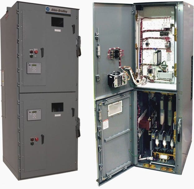
Example of MV MCC Switchgear

Reference: Field Inspection and Testing of New Electrical Equipment – Process Industry Practices (PIP), Construction Industry Institute
Copyright Notice
This technical article is protected by U.S. and international copyright laws. Reproduction and distribution of PDF version of this technical article to websites such as Linkedin, Scribd, Facebook and others without written permission of the sponsor is illegal and strictly prohibited.© EEP-Electrical Engineering Portal.
Related electrical guides & articles
Premium Membership
Get access to premium HV/MV/LV technical articles, electrical engineering guides, research studies and much more! It helps you to shape up your technical skills in your everyday life as an electrical engineer.
More InformationEdvard Csanyi
Hi, I'm an electrical engineer, programmer and founder of EEP - Electrical Engineering Portal. I worked twelve years at Schneider Electric in the position of technical support for low- and medium-voltage projects and the design of busbar trunking systems.I'm highly specialized in the design of LV/MV switchgear and low-voltage, high-power busbar trunking (<6300A) in substations, commercial buildings and industry facilities. I'm also a professional in AutoCAD programming.
Profile: Edvard Csanyi


Hi
How to establish MCC and iMCC testing procedure and lab .
HAs anyone answered this yet?
thanks for consideration
Hi,
I am looking to get some quotes on testing MCC which includes:
Factory tests
Dielectric tests
Operational tests
short circuit tests
panel board tests
Functional Performance tests
Would you please provide me a tentative quote.
Thanks,
Ambreen
832-660-5506
Hi,
Can you please suggest a test equipment to test contactor ride through device to check ride through cycles/ drop-out time if power dip occurs.
Thanks