
Estimated Study Time: 18 minutes
Cable tray type, ducts and conduits
Although the type of cable and conductor is the determining factor in the fire behaviour of ducts and conduits, the choice of cable tray type and the installation of the latter in line with installation precautions are just as crucial.
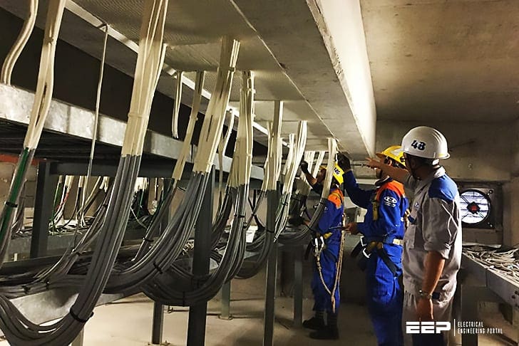 Fire behaviour and construction safety precautions for installation of cables and conductors photo credit: Tuyen Lam Technology Electromechanics Co., LTD
Cables are very rarely the source of a fire. This would only occur if the cable was overloaded to a point at which its insulation melts and inflames materials in the vicinity, or if it short-circuited due to mechanical damage.
Cable ducting is therefore not a potential source of fire.
Routing in rooms, ceilings or service ducting and feeding through partitions promotes air flow, potentially creating chimneys for gases and smoke and representing an energy source capable of causing arcs and secondary short circuits which can encourage the spread of fire.
Therefore, at this stage of a fire they constitute a fairly significant thermal load.
1. Assessment of the fire risk
The potential risk of fire damage to cable ducting and the potential consequences of a resulting spread of fire can only be assessed on a case by case basis. The tables 1 and 2 below offer a preliminary approach.
Understanding the conditions of external influences in relation to materials handled or interposed (BE1 to BE4 according to IEC 60364-5-51, which defines among other things the fire risk), enables a suitable type of cable to be selected.
Table 1 – Level of stress according to business sector
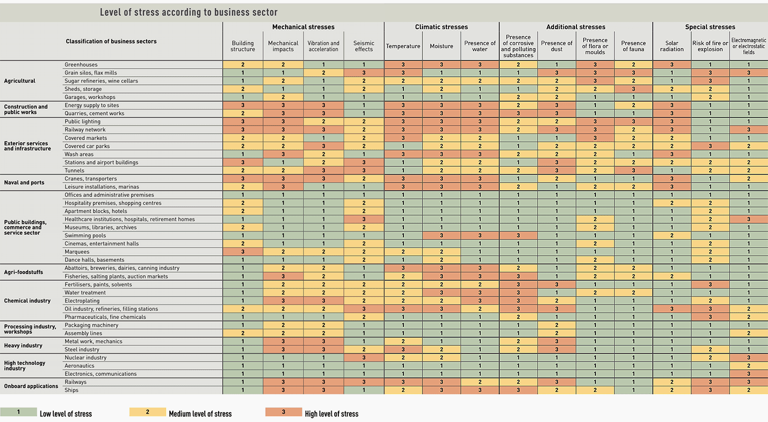
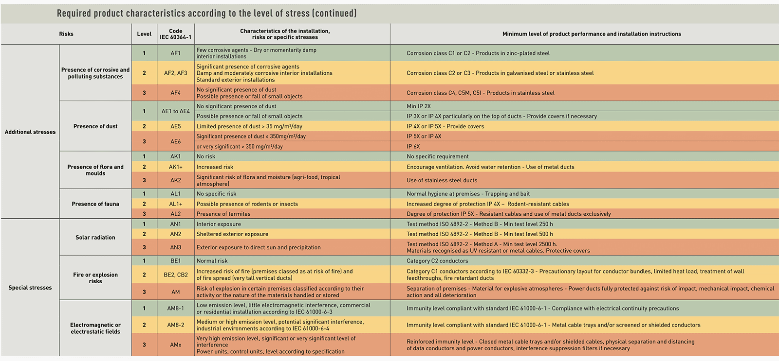
Table 2 – Required product characteristics according to the level of stress
2. Fire behaviour of cables and conductors
2.1 Fire response
The classification of fire behaviour is based on a number of tests which are defined in accordance with international standards (IEC 60331 and IEC 60332), European standards (En 50200) or national standards for certain types of cables (for example French standard NF C 32-070 for category C1).
There are 3 categories of “fire response” rating:
- C3: no special characteristic
- C2: flame-resistant. the majority of cables used in installations belong to this category.
- C1: flame retardant. The use of cables in this category limits the risk of the spread of fire in cable layers and trunking.
In situations where the risk of the spread of fire is high (long vertical ducts) or when the safety if the installation is essential, C1 category cables must be used.
2.1.1 Halogen-free cables
Most cables used today are insulated partially or wholly with polyvinyl chloride or PVC (U 1000 R2 V, H07 VVH2-F, H07 VU, etc.). These conductors are naturally flame-retardant due to the presence of chlorine and offer good levels of fire resistance.
They are normally classified as C2 (flame-resistant) and contribute to the intrinsic safety of installations.
The disadvantage of PVC – If conductors are caught in a fire, hydrogen chloride is emitted which as a gas is an irritant, but this does have the advantage that it allows detection of the outbreak of fire due to the pungent odour that is released. It should be noted that hydrogen chloride is not classified as toxic in the ISO/TC 92/SC 3 report.
The major lethal risk relates to carbon monoxide.
The areas must therefore be decontaminated as quickly as possible.
It must be remembered that the requirement to protect these systems and to expel chlorine led to the development of C1 cables, known as halogen-free cables, with flame retardant composed of aluminium trihydrate or magnesium dihydrate.
These cables emit little smoke and corrosive elements.
2.2 Fire resistance
“Fire response” categories assess the flammability of cables but make no indication of their capacity to maintain supply to installations in the event of fire. In order for safety circuits to continue to function, cables certified for their “fire resistance” must be used.
There are two different categories of “fire resistance”:
- CR2: no special characteristics
- CR1: fire resistant.
Although the type of cable and conductor is the determining factor in the fire behaviour of ducts and conduits, the choice of cable tray type and the method of its installation in compliance with installation precautions are just as crucial.
3. Installation precautions
3.1 Routing and layout of cable layers
The layout of cable layers and groupings as well as individual cables themselves within these layers plays an important role in the development of a fire.
Cables must be laid out in an orderly fashion, limiting gaps between them wherever possible in order to prevent a “kindling” effect which would intensify the fire.
Dense, tight and compact layers are the least likely to catch fire, but in turn their capacity for heat dissipation is lower, which can lead to reduced current-carrying capacity.
Broadly speaking, layouts which create natural “chimneys” must be avoided: this principle applies not only to conductors themselves but also to cable layers and layers with elements in the surrounding environment (walls, ceilings etc).
3.2 The layout of vertical layers
Vertical layouts of layers create a chimney effect which is increased by proximity to a wall or a structure parallel to the layer. A distance d of at least half the width L of the layer must be maintained to reduce this effect, otherwise a perpendicular layout may be preferable.
3.3 Layout of horizontal layers
It is advisable to position layers beneath ceilings at a distance d1 > 2 x W (at least twice the width of the cable tray).
In the event of fire, this will in part prevent a situation where the cables are positioned in the hottest of the gas layers. In order to prevent fire spreading from one layer to another, a minimum distance of d2 > W is also advisable.
3.4 Specific layouts in the vicinity of ducts
Electrical ducts must not be exposed to the risk of harmful temperatures due to proximity to heat sources (air, water or smoke vents, etc). If adequate distances cannot be complied with, screens or thermal insulation must be placed between the gaps.
3.5 Cable entries into enclosures
Leading cables into cabinets can create entries liable to spread fire into the cabinet (in the case of an external fire) or into the environment (in the case of an internal fire).
In practice cable entries in the bottom part of the cabinets or enclosures should be preferred. Fire will be better contained within the enclosure and, in the case of an external fire, the area at ground level is typically less exposed to risk.
However, if cables do have to be led into the top, they should be carefully sealed in. Cable routing must be sealed using cable clamps or similar devices.
These precautions should be followed in particular where an enclosure has entries both at the top and the bottom, since a chimney effect could accelerate the growth of a fire.
3.6 Wall feedthroughs
Compartmentalisation is one way to obstruct the development of a fire by sealing volumes and thereby preventing it spreading. Regulations typically define the technical criteria to be followed when creating fire compartments by fire resistance duration categories known as “fire ratings” that are expressed in hours.
Clearly the ideal solution is to review and plan conductor ducts and their wall feedthroughs during a building’s planning stage.
In reality, changes in usage often require multiple alterations, reconfigurations or removals to be made, requiring minor or major modifications to be implemented in the installation, from the simple feedthrough of additional conductors in existing ducts to the addition of new ducts altogether.
During these alteration works priority tends to be given to the electrical aspect of the work rather than to fire safety, particularly given the fact that the constraints imposed by the existing infrastructure are coupled with the requirement to maintain operating continuity.
A number of fires are caused by the lack of any upgrade following multiple works where the objectives and the original performance levels have been forgotten with the changes over time. Restoring the “fire rating” is thus a crucial operation.
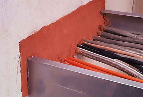
3.6.1 Cable tray feedthroughs and trunking
The underlying principle is the need to fill the cavity created by the duct, both externally and internally. The latter can be waived if the interior section does not exceed 710 mm² and if the duct has at least an IP 33 rating, including at its end.
Where possible, the cables should also be protected over a distance of at least 20 cm on either side of the feedthrough.
Intumescent pads
These have a special feature in high temperatures, whereby they inflate to form a type of non-combustible and thermally insulating foam.
They can expand to up to 8 or even 10 times their volume. They prevent the spread of fire by blocking off the wall or partition feedthrough.
It is also possible to use malleable intumescent plaster or mastics in cartridge guns, but it is important to take their maximum temperature into account.
High density mineral wools (140 kg/m³)
These offer good temperature resistance (around 1,000°C). However, installing panels can be problematic in irregularly shaped cavities, and their relative mechanical fragility does not always permit them to be reused properly after additional cables have been fed through.
Plasters
These are rightly considered to be one of the best protections against fire and rising temperatures. Composed of gypsum and water, they are nonpolluting and non toxic. Plasters are used in the form of plasterboard (for fire sleeves, partitions, etc.), as a surface coating or as a filler.
The quality of the installation must be perfect in order to avoid leaving any cracks, as any further modifications will require the plaster to be broken.
Filling in the cavity in direct contact with the cables is not advisable due to the risk of the filling being only partial and the grip on certain types of cable insulation being inadequate.
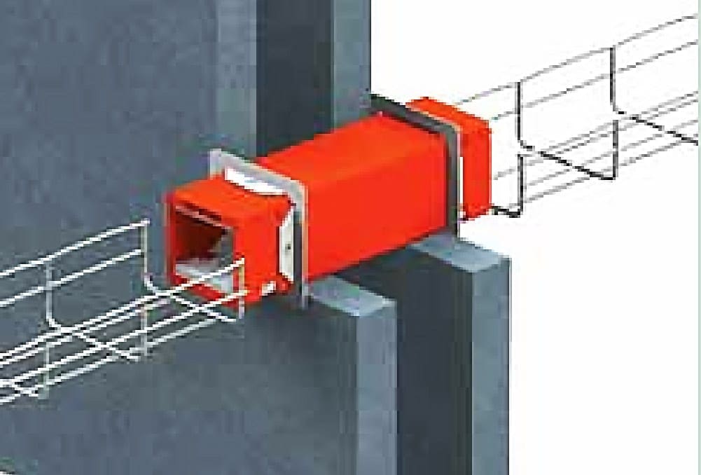
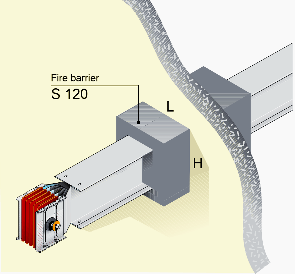
3.6.2 Prefabricated busbar feedthrough
As long as the filling around the sleeves is completed correctly (for example with plaster), prefabricated busbars with a protection rating of at least IP 54 ensure wall feedthroughs do not promote the spread of flames.
Without official certification from a qualified body for a layout of this kind, the best solution is to use fire-barrier elements as recommended by the manufacturer.
Source: Transport and distribution inside an installation by Legrand
Related electrical guides & articles


Edvard Csanyi
Hi, I'm an electrical engineer, programmer and founder of EEP - Electrical Engineering Portal. I worked twelve years at Schneider Electric in the position of technical support for low- and medium-voltage projects and the design of busbar trunking systems.I'm highly specialized in the design of LV/MV switchgear and low-voltage, high-power busbar trunking (<6300A) in substations, commercial buildings and industry facilities. I'm also a professional in AutoCAD programming.
Profile: Edvard Csanyi

important subject for hot regions, thank you
hopefully, add name of fire protection material used in cable duct holess
Is your organization familiar with Ellis Cable Cleats as a mission critical safety product that provides protection in the event of a short-circuit fault? https://www.youtube.com/watch?time_continue=46&v=_i2L-CCJoDI
All articales save to topic by topic