Estimated Study Time: 17 minutes
Synchronization to the grid
Any power plant commissioning, from small industrial GTG (Gas-To-Gasoline) to nuclear facility, will converge to a very final step before (provisional) commercial operation, sometimes empathized as “first kW”: synchronization to the local or national grid. This is in fact a very critical phase of the installation, where mistakes in pre-commissioning or forced control variables to bypass that last permissive prevention to close the main MV breaker can easily lead to a disaster.
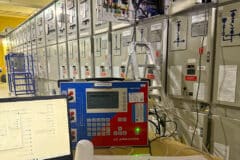
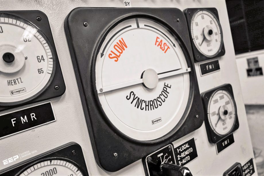 My experience in the first synchronization of the MV generator in an industrial plant (original photo by Francesco Becattini)
As common sense would suggest, synchronization of generator and grid implies that three key parameters of the two waveforms match within a certain window:
- Frequency
- Voltage
- Phase Angle
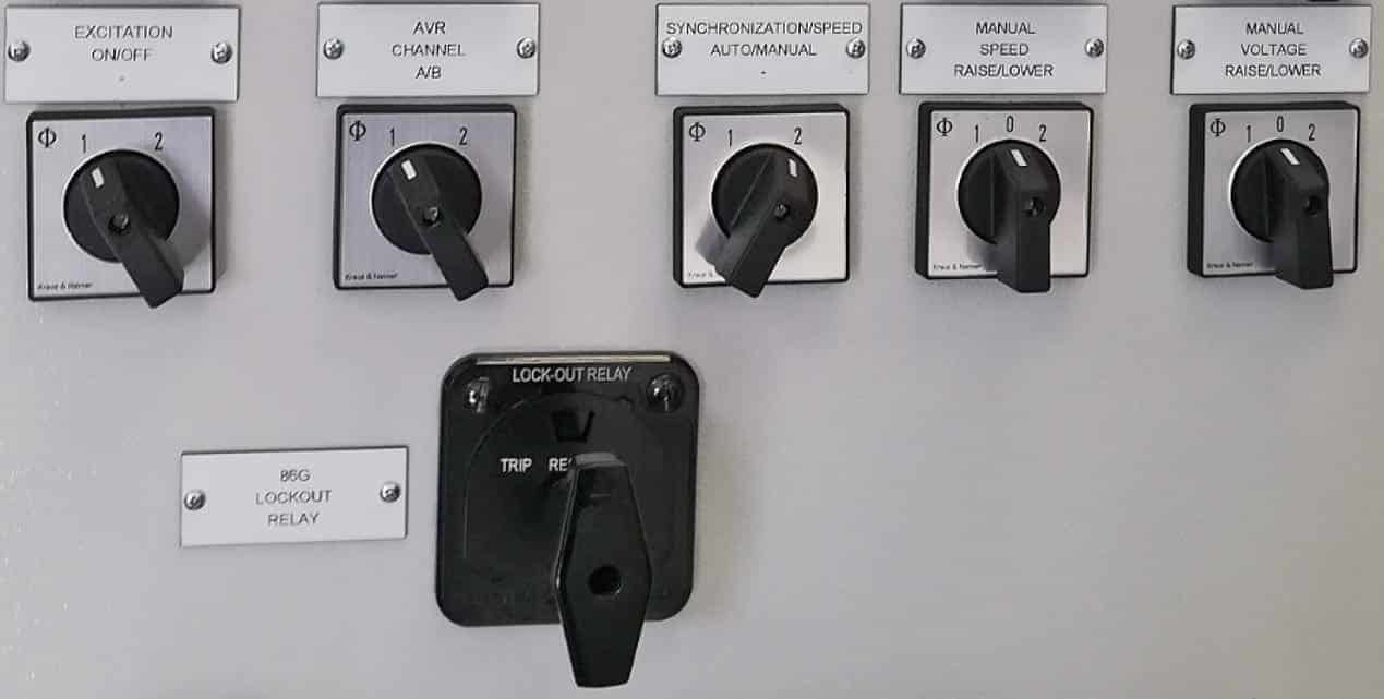
This condition is verified by a synchro check device, that may be integrated in the main IED protecting the generator as ANSI 25C function and obtained acting on governor and AVR either manually or via an automatic synchronization card, that will send the closing command to the MV switchgear control circuitry finally closing the main circuit breaker (52G).
Check on instrumentation and protection
Before initiating the synchronization sequence, regardless of the fact that all factory test reports, pre-commissioning, and commissioning certificates are available a final check of proper protective functions in the live condition is due.
To perform this key activity all the instrumentation connected to the protection relay including VT via (possibly) primary and secondary injection, and CT via polarity test must be rechecked. Obviously, all other subsystems including prime mover and driven skid shall be fully commissioned, hardwired control loops checked (with special focus on trip signals), communication (soft link) established.
All panels including the MV Switchgear station and excitation panel (AVR) shall be energized and ready.
In phase 2 earth switch is closed to start the short circuit tests, which will imply a soft ramping of excitation current and measuring armature currents at different field excitation current. An ANSI 87 (differential) protection is simulated changing the ratio of one CT.
In this phase, both proper excitation system functioning and actions of a differential system that is one of the cornerstone protections will usually trigger both a prime mover trip and a fast de-excitation of the generator.
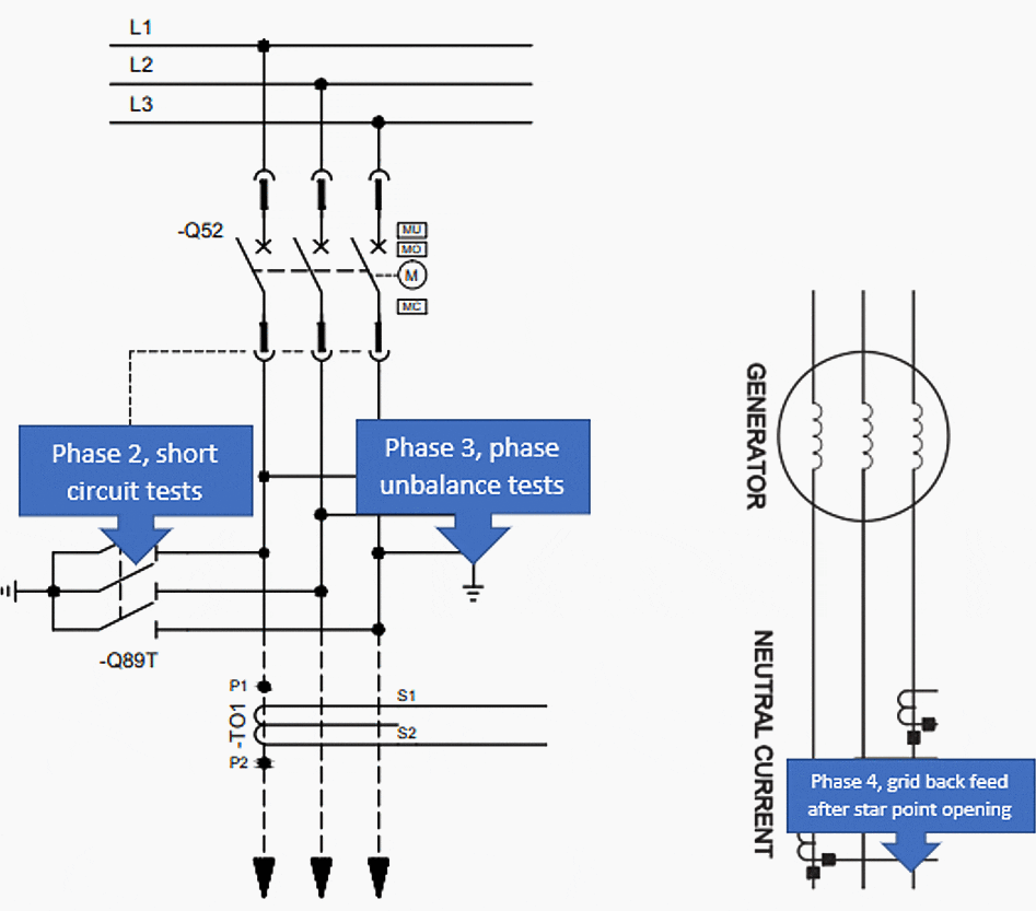
Phase 3 will involve an unbalance of the three-phase system connecting to the ground one of the phases and obviously removing the shorting link, in this way 51G and 67N protection (via toroidal or ZCT) will be tested.
Phase 4 will finally check the phase sense of rotation after back feeding the system (closing 52G breaker after opening the star point link), phasor visualization of a digital protective relay will help to check that rotation is coherent. Finally, voltage waveforms (usually phase to phase, e.g. U to V secondaries) to synchro check system and automatic synchronization system are measured and visualized.
Now the synchronization system has all the inputs (and a working protective relay as a backup in case of troubles) to interconnect our system to the grid.
Voltage and frequency
Grid frequency is usually a very stable parameter, and definitely, it will be during a plant synchronization (you don’t want to connect a new unit to the grid during a thunderstorm!). For historical reasons, two main values coexist, 50Hz and 60Hz, and prime mover, usually after being duly commissioned, has no trouble reaching the revolutions per minute needed to match the grid value.
Matching the voltages is on the contrary a little trickier. For MV applications in fact it is unpractical to have a direct measuring of the voltage, a potential transformer (PT or VT) is hence interposed and readings are hence affected by the ratio and performance of the two devices used to measure the voltage upstream and downstream the breaker object of the synchronization.
Since usually, the upstream VT is part of an existing MV equipment, unless the plant is totally a greenfield installation, accuracy versus the device downstream the (possibly new) MV breaker may differ significantly. The secondary value may differ, e.g. in Europe, the industry-standard moved from 100V line to line to 110V line to line during last year and upstream voltage may be affected by a tap changer position of an upstream transformer, possibly in a part of the plant that is not accessible for a CHP or other continuous cycle production plant.
What will happen e.g. if the VT upstream is marked on the schematics as brand new 110V secondary, while actually is still the old 100V device and at the same time the upstream transformer tap changer is not in null position but it is raising the busbar voltage of exactly +10% (e.g. due to plant need, e.g. some operator may have acted on the tap to compensate a reactive power compensator bank temporary offline)?
In this scenario, you may have perfectly adjusted the automatic synchronizer and synchro check, but there is no possibility to avoid a breaker closure that will trigger a massive reactive power flow from the grid since the actual voltage difference is way above the permitted delta.
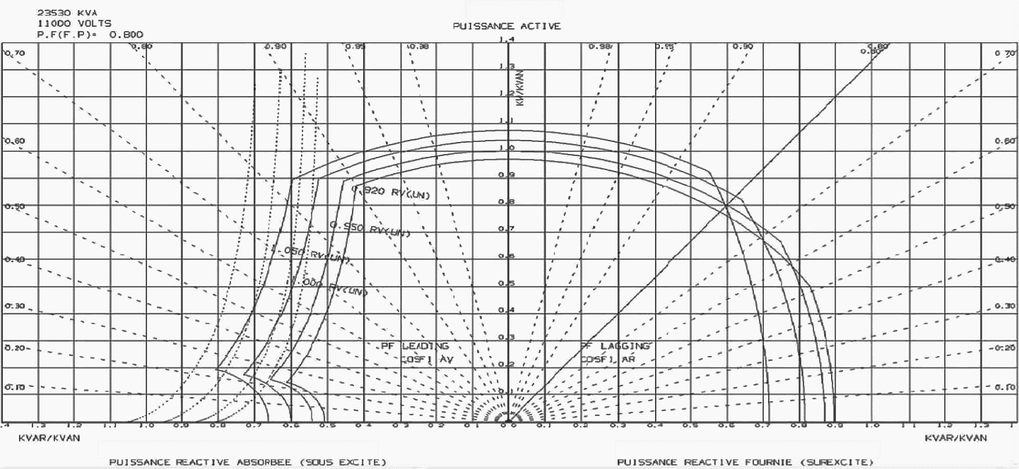
In this scenario either the AVR increases the field (excitation) current, which is unlikely since due to the above double mistake the AVR is not aware to be in under excited state… and to increase field current will be against the overexcitation limiter logics, or a trip will happen.
Since you are affecting the reactive power flow from the grid this trip may occur at grid breaker level, that is what you do not what to experience in a CHP installation since a full outage will take hours to recover, apart from the mechanical stresses on the machines (especially a brand new prime mover like a gas turbine) due to a sudden trip.
Another source of trouble is the fact that due to cost considerations sometimes there is not a VT immediately upstream and downstream the breaker you have to synchronize, especially when a step-up transformer is included in the plant.
While voltage could be easily compensated via a different primary to secondary VT ratio, assuming that no tap-changer is installed, either on load or off-load, there is a more hidden risk associated with a transformer insertion. The Vector group of typical Dyn11 equipment will in fact add a 30° displacement between upstream and downstream waveforms.
Related electrical guides & articles


Marco Bruschini
Chartered engineer with +10y of experience in electrical rotating and static equipment engineering procurement and installation, for renewables (hydroelectric) and natural gas plants. industrial and O&G markets (onshore and offshore). Genuine interest for energy transition and electrification, with a focus on integration of new energy sources in national grid and digitalization of control system and plant automation, including remote diagnostic.Profile: Marco Bruschini