
Estimated Study Time: 36 minutes
Substation Construction Issues
High-voltage substations—especially modern AIS/GIS installations up to 400 kV—are engineered with extreme precision. Every cable, conductor, grounding conductor, insulator, and steel structure is designed according to exact assumptions: soil models, thermal limits, mechanical forces, environmental conditions, lightning protection angles, and the performance characteristics of CTs, VTs, and relays. In theory, these designs form a flawless system. In reality, however, substations face a critical challenge: construction rarely follows every engineering requirement.
 Five Construction Issues That Do Not Follow the Engineering Design (And Why They Matter)
Small deviations—incorrect gravel thickness, a grounding conductor shifted by 40 cm, a shield wire tensioned on a hot day without adjustment, or a cable tray more tightly packed than expected—appear harmless during construction.
But in a high-energy environment, small inconsistencies become major risks:
- Elevated step and touch voltages
- Equipment overstress
- Lightning protection failure
- Overheated cables
- CT saturation and protection blindness
- Premature insulation breakdown
These issues emerge across EPC (Engineering, Procurement, and Construction) projects worldwide—especially during fast-track renewable energy connections—and they have significant impact on safety, reliability, and long-term performance.
- Grounding Studies vs Real Construction Practices:
- Sag and Tension Study Not Implemented Correctly:
- Cable Distances and Grouping Deviating From the Thermal Study:
- Why Installation Method Matters (Buried, Ducts, Troughs, or Trays)
- Why Small Spacing Changes Cause Big Temperature Differences
- When Multiple Cables Per Phase Are Used, Risk Multiplies
- LV Cables in Trenches: A Hidden but Serious Problem
- Construction Deviations Commonly Observed
- Practical Recommendations for Construction Teams
- CT/VT Requirements Not Followed
- MV Cable Bending Radius Violations
- Final Words
- Attachment (PDF) 🔗 Download ‘Documents and Drawings for Plant Design, Supply and Installation of 230kV and 132kV Substations’
1. Grounding Studies vs Real Construction Practices
Grounding design is one of the most safety-critical components of any substation. When executed correctly, it ensures that under single-line-to-ground (SLG) fault conditions, dangerous voltage gradients—touch and step voltages—remain within the limits defined by IEEE or IEC standards.
However, between civil works, construction sequencing, and cost-driven on-site decisions, grounding requirements are among the most frequently violated aspects of substation construction.
1.1 Gravel Thickness Not Following the Grounding Study
The grounding study typically assumes a surface layer (gravel or crushed rock) with:
- Controlled resistivity (ρs), usually 2,000–3,000 Ω·m
- Controlled thickness, often 10–15 cm
- Uniform distribution across energized areas
This layer forms a high-resistivity surface barrier that reduces the current entering the human body during a fault.
What happens in construction?
- Gravel layer is thinner than specified (e.g., 3–5 cm instead of 10–15 cm).
- Gravel is non-uniform, especially around foundations, fences, or cable trenches.
- A cheaper material with lower resistivity is substituted.
- Heavy machinery compacts the gravel, reducing its effective resistivity.
- Areas are left exposed (corners, around ducts, near building walls).
Why it matters?
It matters because reduced gravel thickness lowers surface resistivity, which directly increases step and touch voltages. Hot spots that were safe during the study become dangerous in reality.
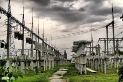
Figure 1 – Old Substation with non-uniform gravel layer
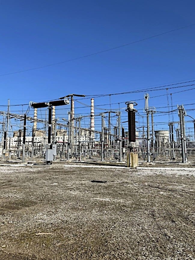
Field symptoms include:
- Commissioning test failures
- High step potential around transformer legs and GIS building edges
- Dangerous gradients near grounding electrodes
In extreme cases, a worker standing on a wet, compacted, or missing gravel patch may experience voltage exposure significantly above safe limits.
1.2 Water-Insulating Layers Under Foundations (Unintended Electrical Insulation)
Modern substations frequently include civil requirements for water resistance:
- Bituminous membranes
- PVC/HDPE water barriers
- Waterproof concrete coatings
- Chemical sealing layers
These materials are excellent for waterproofing—but they act as electrical insulators.
Observed construction practices
- Entire building foundations are covered with waterproof membranes.
- Vertical foundation walls are coated with bitumen or plastic layers.
- Soil-improvement gravel pads under foundations are several tens of cm thick.
- Buildings sit on high-resistivity layers not modeled in the grounding study.
Why this is a problem?
Grounding studies assume that building foundations, rebar cages, and concrete structures are electrically bonded to soil. Concrete has good conductivity due to moisture and ionic content.
- The concrete loses its natural conductive path.
- The building “floats” electrically.
- Step and touch voltages around building edges increase.
- Fault current distribution becomes uneven.
- Grounding resistance increases.
Typical consequences
- Dangerous gradients around the building perimeter
- Uncontrolled potential rise inside control rooms
- GIS or control building grounding not behaving as modeled
- Need for retrofitted external ground rings or copper plates
In worst cases, the grounding design becomes invalid, even if the grounding mat itself is correct.
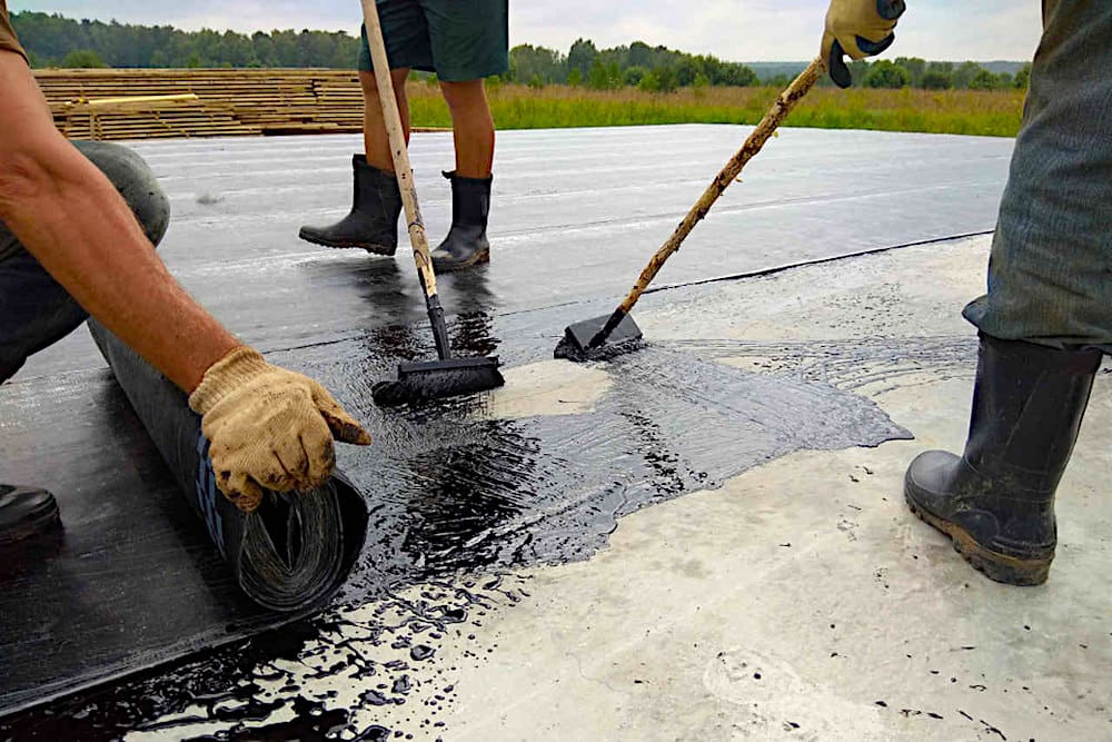
Figure 2 – Substation Bitumen Waterproofing as a Very Bad Practice
1.3 Incorrect Grounding Mat Layout & Enlarged Openings
Ground grids are designed with specific conductor spacing—often 6 m × 6 m or similar—to control voltage gradients across the substation. Every conductor, bond, and mesh opening affects the electric field distribution.
Common deviations
- Mesh spacing becomes larger due to construction shortcuts.
- Some grid connections are omitted as “unnecessary”.
- Ground rods are reduced or replaced with shorter ones.
- Conductors are rerouted around obstacles (cable trenches, ducts, pits).
- Mesh alignment shifts due to tolerances in excavation.
Why larger openings are dangerous?
Larger mesh openings increase the potential gradient between adjacent points, leading to:
- Higher step voltages
- Higher touch voltages, especially near equipment structures
- Uncontrolled hot spots around transformer foundations, fences, and tower legs
- Poor equipotential bonding in heavily loaded areas
The grounding design relies on the density of the grid to maintain safe voltage differences. When the spacing is increased even by 0.5–1 m, the model is no longer valid.
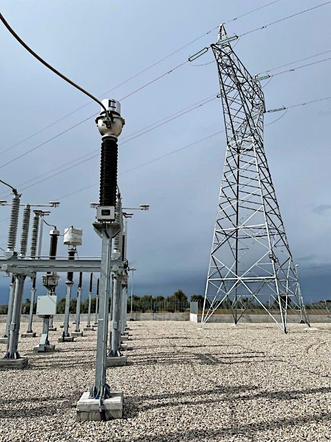
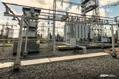
Figure 3 – Substation with a Perfect Gravel Layer According to Study
1.4 Soil-Improvement Layers Not Included in the Soil Model
During construction, contractors often add soil-improvement layers to stabilize ground or improve drainage:
- Thick gravel layers
- Compacted crushed rock
- Sand layers for leveling
- Imported fill with unknown resistivity
- Geotextile layers separating fill from native soil
Why this undermines the grounding study
Grounding studies are built on soil resistivity measurements taken before construction. If the soil profile changes during civil works, the real resistivity distribution is no longer the one modeled.
Typical impacts are:
- Increased top-layer resistivity → higher touch voltages.
- Modified depth of the native soil → inaccurate grid resistance calculation.
- Poor grounding system performance even if grid layout is correct.
Critical problem
Contractors often perform soil-improvement after the grounding study without informing engineers. The first time the problem is discovered is during commissioning tests—when it’s too late.
Ouch!
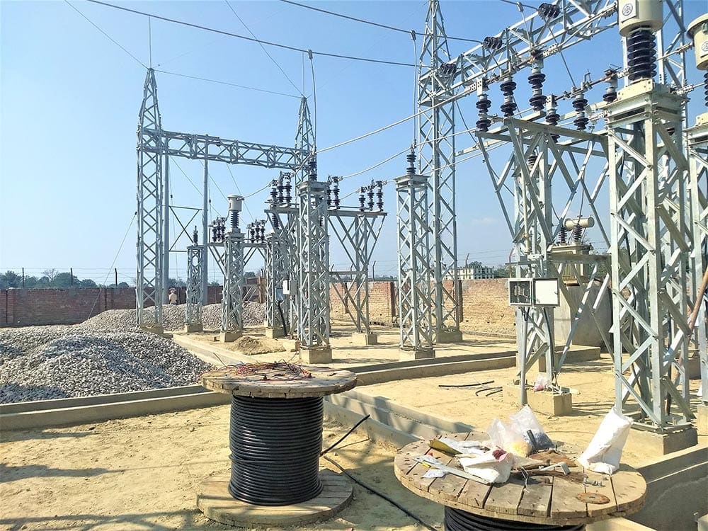
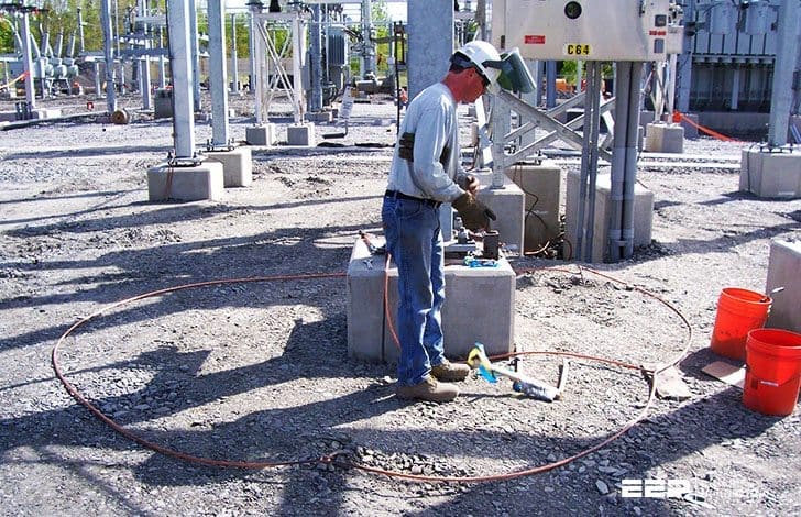
Figure 4 – Overhauling of gravel surface of switchyard at 33/11 kV Substation
1.5 Poor Soil Resistivity Measurements Due to Fill Layers
In some cases, measurements are taken after soil improvement or on disturbed ground. This produces artificially high or low resistivity values, leading to:
- Incorrect design of the grid
- Underestimation of required conductor density
- Misleading conclusions about necessary ground rods
- Incorrect modeling of multilayer soil
What are the On-site consequences?
- Grid resistance not reaching target
- Need for unplanned deep earth rods
- Need for perimeter enhancement (ground rings, backfill materials)
Figure 5 – Substation Soil Resistivity Measurements
1.6 Summary
Grounding is one of the most sensitive disciplines in high-voltage substations. What looks like a small civil deviation—5 cm less gravel, a waterproof membrane, a shifted grounding conductor—can have massive electrical consequences.
These construction deviations often introduce:
- Elevated step & touch voltages
- Inaccurate potential distribution
- Increased grid resistance
- Unsafe working conditions
- Failed commissioning tests
- Expensive retrofits
- Long-term operational risk
To ensure safety and design compliance, grounding design assumptions must be preserved from first excavation to final commissioning. Construction teams must understand that grounding is not just copper in the ground—it is a complete system, where layers, materials, soil structure, and geometric accuracy all matter.
Suggested Course – Advanced Course in Proper Grounding and Fault Mitigation
2. Sag and Tension Study Not Implemented Correctly
Sag and tension studies are among the most precise mechanical calculations in a substation project. Electrical engineers use these studies to determine the exact mechanical behavior of both power conductors and shield wires (OPGW/earth wires) under a wide range of climatic conditions. These studies account for conductor weight, wind pressure, ice loading, thermal expansion, and ruling span geometry.
Their purpose is simple yet critical: ensure that conductors operate safely without overstressing equipment, structures, or foundations.
Related electrical guides & articles


Thiseas Violantis
Thiseas Violantis is an Electromechanical Engineering Manager with a Master’s degree in Electrical Engineering, specializing in primary design for AIS and GIS substations up to 400 kV. He has worked on some of the most complex high-voltage projects in Greece, contributing across design coordination, technical oversight, and field implementation to ensure safe, reliable, and standards-compliant infrastructure.Profile: Thiseas Violantis
