
Estimated Study Time: 60 minutes
Selection Of Protection For Mitigating Extreme Contingencies
Extreme contingencies typically indicate events that lead to the unavailability of numerous power system components or a cascading failure, such as the loss of transmission lines along a common right-of-way or faults with delayed clearance (e.g., a jammed breaker or protection system malfunction) in a bus section. Extreme contingency assessments are typically performed to evaluate their impact on power system performance and to measure the system’s robustness.
 Five phenomena that could collapse the entire power system
Some of the largest blackouts with durations in days and weeks that happened recently were in Dominican Republic (November 2025), Cuba (late 2024 – 2025), Iberian Peninsula – Spain, Portugal, France, and Andorra (April 2025), Pakistan (2015, 2021, 2023), Bangladesh (2014, 2022), Brazil and Paraguay (2009), Venezuela (2019) and many other countries.
Interestingly, if you analyze blackout statistics for power systems worldwide in the past 30 years, you will notice that the number of blackouts increased almost exponentially. One would say that things are getting more and more complex…
Emergency Protection Systems (EPSs) are globally employed to enhance grid security against extreme contingencies in regions where emergencies like these are frequent and/or result in significant consequences, including load loss or system failure.
Naturally, it is not practical or even possible to foresee or stop every possible contingency event that could happen at random and cause the power system to fail. A modest number of Emergency Protection Systems (EPSs) are most likely enough to sufficiently protect a system when its complexity is low.
Large systems, however, either a defense strategy or a series of coordinated actions, both of which must be extremely difficult to design and implement. This is required to guarantee that the system can handle any significant shaking that may develop.
Consequently, we have opted to categorize the many methods of action based on potential power system phenomena rather than the circumstances themselves.
The following paragraphs will provide a short review of the main characteristics of these phenomena, of the main factors pointing to the type of Emergency Protection System that will prevent a loss of system integrity, and of the various EPS action types.
- This is Why the Loss of Power System Integrity Happens:
- Main Factors in the Selection of the Appropriate Protection Actions:
- What Measures Can be Taken Against Power System Collapse:
- Detailed Description of Various Emergency Protection System Action:
- Generation Rejection
- Turbine Fast Valving
- Fast Unit and Pumping Storage Unit Start-up
- Automatic Generation Control Set Point Changes
- Underfrequency Load Shedding
- Undervoltage Load Shedding
- Remote Load Shedding
- Automatic Shunt Switching (Shunt Reactor/Capacitor Tripping or Closing)
- Braking Resistor
- HVDC Fast Power Change
- Controlled Opening of Interconnection
- Tap Changer Blocking and Setpoint Adjustment
- Quick Increase of Synchronous Condenser Voltage Setpoint
- Final Thoughts
- Attachment (PDF) 🔗 Download ‘A Handbook On Electric Power Systems – Generation, Transmission, Distribution, and Consumption’
1. This is Why the Loss of Power System Integrity Happens
The loss of power system integrity caused by extreme contingencies will always be characterized by one or more of the following phenomena:
- Transient angle instability;
- Frequency instability;
- Voltage instability;
- Small signal angle instability;
- Cascade tripping.
The main purpose of this technical article is to discuss main aspect of power system phenomena to help in the selection of the most appropriate EPS. Cascade tripping is not, strictly speaking, a power system phenomena but nevertheless discussed here considering its importance.
1.1 Transient Angle Instability
The transient stability of a power system refers to the capacity of all generators to sustain synchronism when faced with a significant disruption, such as a substantial current fault, the loss of major generation, or the loss of an important load block. The system response will involve substantial fluctuations in generator angles and considerable changes in real and reactive power flow, bus voltages, and other system parameters.
The loss of synchronism might impact a single generating unit, a power plant with numerous units, a specific network region, or several interconnected regions. The loss may manifest abruptly (during the initial swing) or following to a sequence of divergent swings.
Just to note that the likelihood of loss increases when the system is loosely interconnected or when power flows are high.
The latter may substantially boost the risk of swift disconnection of units and system separation due to malfunctioning line protection relays.
Figure 1 – Operating limits of synchronous generator with three operating points

1.2 Frequency Instability
Frequency stability refers to a power system’s capacity to keep the system frequency within an acceptable range during standard operational conditions or following a significant disturbance. In the event that network separation occurs despite implemented control measures to preserve network integrity, it is crucial to mitigate frequency jumps.
Generators may function unrestricted within ± 0.5 Hz of the nominal frequency (50 or 60 Hz system) and for a limited duration beyond these parameters, as dictated by the manufacturer’s specifications.
A significant issue for a steam turbine is the frequency decline caused by an sudden loss of generation. This is particularly difficult if the pre-disturbance power transfer values across regions of the power system are significant.
In the network region with excess power generation, system frequency will begin to rise. If the overfrequency is not mitigated within a predetermined timeframe, the unit will be tripped due to the unstable boiler condition. The issue of overfrequency is less concerning than that of underfrequency, as the tripping of the unit will result in a decrease in frequency.
Nevertheless, if the decrease proves insufficient, additional generating units must be disconnected, potentially leading to an underfrequency condition if executed excessively.
Watch Video – Frequency stability
1.3 Voltage Instability
Voltage stability refers to the capacity to maintain steady and acceptable voltage levels at all buses during normal conditions and following a disturbance. Voltage instability arises when loads attempt to be restored above the maximum power capacity of the combined generating and transmission system.
The maximum power is directly affected by the electrical distances between generation and load centers, together with the reactive power constraints of generators.
Voltage instability manifests as a gradual decline in voltage at the transmission level due to load restoration effects. The decrease in voltages may lead to a system failure characterized by generators losing synchronism and induction motors stalling.
Regarding long-term voltage stability, the primary issue is the loss of transmission infrastructure (mostly between generating and load centers) or the disconnection of generators (particularly those located near the loads and maintaining their voltage levels). With respect to short-term voltage instability, the slow clearing of a fault may cause an induction motor dominated load (e.g. air conditioning) to become unstable.
Watch Video – Voltage stability
Voltage stability has emerged as a key issue in the design and operation of electric power systems due to the increasing need for power transfers. Increasing power transfer over long distances or calling on reactive power reserves are two ways in which load increases and generation rescheduling strain the system.
Always keep an eye on the transmission system’s loadability limit. Whenever the load becomes excessive, measures like load shedding must be implemented to alleviate the strain on the transmission system.
1.4 Small Signal Angle Instability
Small signal stability represents the capacity of the power system to preserve synchronism when faced with a small disturbance. Power systems have numerous oscillation modes resulting from diverse interactions among its components.
Many of the oscillations are due to generator rotor masses swinging relative to one another.
The damping of electromechanical modes is a crucial characteristic for secure operation in many systems, especially following an extreme crisis.
Figure 2 – Power system stability chart with Small signal angle marked

1.5 Cascade Tripping
Cascading denotes an uncontrolled series of disconnections in transmission lines initiated by an event at a single location. In certain circumstances, a significant disruption in a transmission system can trigger large oscillations in real and reactive power flows, as well as instability in voltage levels.
These oscillations can trigger certain protection devices or control systems, potentially leading to uncontrolled cascading tripping of lines and generators.
Cascaded line tripping may also result from overload or thermal issues. Cascaded line tripping will impact interconnections between power system regions and will be especially problematic when one region is importing electricity while another is exporting. In such circumstances, the repercussions of a disturbance may extend throughout a vast system region, potentially leading to the loss of supply for numerous consumers.
This increases the power flow on the remaining lines and may result in load encroachment into the backup characteristics of distance relays or may be detected as an overload condition by a time-delayed phase over current relay.
The system dynamics will ascertain which, if any, of the relays are implicated: Zone 3 elements of a distance relay typically operate within around 1 second, whereas time-delayed overcurrent relays configured to identify an overload generally function over several minutes.
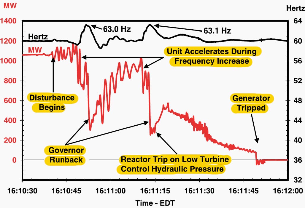
Figure 3 – Events at one large gGenerator during the cascade
To prevent cascaded line tripping, it is essential to maintain sufficient coordination margins between the operational characteristics of all non-unit protection relays employed in the network, and when feasible, to implement high-speed unit or communication-assisted protection methods.
The reliability, security, and specificity of the protective relays and schemes, including their communication systems when applicable, are crucial in mitigating the risk of cascading line tripping.
Nevertheless, enhancing the performance of traditional equipment protection may not entirely prevent the phenomena that result in cascaded line tripping, and Emergency protection systems (EPSs) may be necessary to mitigate their effects on the power system.
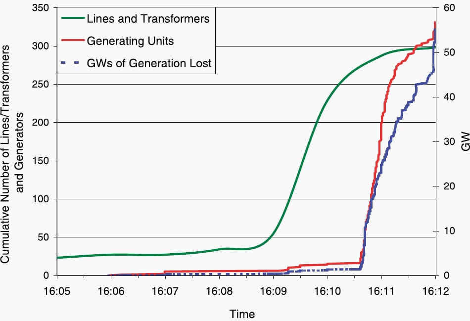
Figure 4 – Rate of line and generator trips during the cascade
2. Main Factors In The Selection Of The Appropriate Protection Actions
The most important factors in the selection of the appropriate means of actions to prevent loss of power system integrity are:
- Scenarios of extreme contingencies;
- Power system structure (meshed, radial …) and size;
- Power system type of interconnection with its neighbors.
2.1 Scenarios of extreme contingencies
To ensure dependable service, a power system must withstand a diverse range of disturbances. Implementing protections against all types of events is impractical due to the substantial cost required for appropriate equipment.
Consequently, power systems are typically engineered and managed to provide stability during more likely contingencies, commonly known as design contingencies.
A closer look of design and operational criteria reveals substantial discrepancies across utilities in their definitions of design contingencies. Furthermore, most utilities build and manage their power systems to ensure that, with all transmission facilities operational and standard processes implemented, the typical customer demand and generation can be maintained following a design contingency.
The aim of extreme contingency analysis is to evaluate the impact of extreme conditions on system performance. This is conducted to assess system robustness or to evaluate the magnitude of a widespread system disturbance, despite a small probability of extreme contingencies occurring.
The extreme contingencies mentioned below aim to identify certain scenarios that may lead to extensive blackouts in the bulk power system. Extreme contingency scenarios are specific to each power system and must be driven by an understanding of its characteristics and historical experiences with significant disturbances.
Related electrical guides & articles


Edvard Csanyi
Hi, I'm an electrical engineer, programmer and founder of EEP - Electrical Engineering Portal. I worked twelve years at Schneider Electric in the position of technical support for low- and medium-voltage projects and the design of busbar trunking systems.I'm highly specialized in the design of LV/MV switchgear and low-voltage, high-power busbar trunking (<6300A) in substations, commercial buildings and industry facilities. I'm also a professional in AutoCAD programming.
Profile: Edvard Csanyi
