
Estimated Study Time: 36 minutes
Transformer analysis
To be clear, nowadays, you can perform dozens of analyses on a transformer, and all of them are very important. However, it should not be that hard to separate a few of them, the most important ones. Let’s discuss insulation, short-circuit strength, efficiency, and voltage regulation in power transformers.
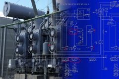
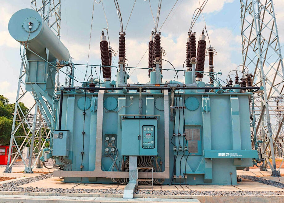 Four most important power transformer analyses (photo credit: Omicron)
One of the most crucial elements in power transformer design is its insulation system, which protects internal components from electrical stresses. Insulation levels are defined based on parameters such as the Highest Voltage for Equipment (Um) and Basic Insulation Level (BIL).
These values determine the withstand capability of the transformer against overvoltages caused by switching operations, lightning strikes, and other transient events.
Proper selection of insulation levels is necessary to prevent failures and ensure compliance with international standards like IEC 60076. The dielectric requirements of a transformer further validate its insulation strength through rigorous tests such as power frequency withstand tests, lightning impulse tests, switching impulse tests, and partial discharge tests.
These tests assess the insulation’s ability to withstand both steady-state and transient overvoltages, ensuring long-term reliability.
Tests such as dielectric short-circuit tests and mechanical short-circuit tests verify whether a transformer can sustain these extreme conditions without experiencing permanent damage.
Failure to ensure adequate short-circuit strength can result in catastrophic failures, leading to costly outages and equipment replacements.
The efficiency and losses of a power transformer significantly impact its operational cost and energy consumption. Losses in a transformer are broadly categorized into no-load losses (core losses) and load losses (copper losses). No-load losses arise due to the continuous magnetization of the transformer core, while load losses occur due to the resistance of winding conductors when carrying current.
Understanding and minimizing these losses are crucial for enhancing transformer efficiency and reducing economic impacts. The article explores the factors affecting these losses, methods of measurement, and techniques for optimizing efficiency.
Voltage regulation is another essential performance parameter in power transformers, influencing grid stability and power quality. Transformers are equipped with tap changers, which allow adjustments in the turns ratio to maintain voltage levels within acceptable limits.
Tap changers are classified into Off-Load Tap Changers (DETCs) and On-Load Tap Changers (OLTCs), each serving different operational needs.
Various tapping arrangements, such as Constant Flux Voltage Variation (CFVV), Variable Flux Voltage Variation (VFVV), and Combined Voltage Variation (CbVV), enable precise voltage control.
Topics discussed in this tecnical article:
- Insulation Levels and Dielectric Requirements in Power Transformers:
- Short-Circuit Strength and Withstand Capability of Power Transformers:
- Efficiency and Losses in Power Transformers (No-Load & Load Losses):
- Tapping Arrangements and Voltage Regulation in Power Transformers:
- Purpose of Tapping Arrangements in Transformers
- Types of Tap Changers in Power Transformers:
- Tap Positioning and Voltage Adjustment Range
- Voltage Regulation and Its Importance
- Types of Tapping Arrangements (IEC 60076-1):
- Considerations for Selecting Tap Changers and Tapping Arrangements
- Testing and Performance Verification
- Attachment (PDF) 🔗 Download ‘Power Transformer Handbook (19.5 Mb)’
1. Insulation Levels and Dielectric Requirements in Power Transformers
Insulation is a critical component in power transformers, ensuring their ability to withstand operating voltages, transient over voltages, and fault conditions. The IEC 60076-3 standard defines insulation levels and dielectric requirements for power transformers, specifying the necessary tests and design considerations to ensure safety and reliability.
Proper insulation coordination is essential to protect the transformer from electrical breakdowns and ensure long-term performance.
1.1 Insulation Levels in Power Transformers
The insulation level of a transformer is determined by its ability to withstand both continuous operating voltages and transient over voltages, such as those caused by lightning strikes or switching events. IEC 60076-3 defines insulation levels based on the highest voltage for equipment (Um) and the corresponding basic insulation level (BIL).
a) Highest Voltage for Equipment (Um)
The highest voltage for equipment (Um) represents the maximum system voltage that a transformer winding can experience under normal operating conditions. It includes margin for voltage fluctuations and system contingencies.
The selection of Um ensures that the insulation system is adequately rated to prevent breakdown.
b) Basic Insulation Level (BIL)
The Basic Insulation Level (BIL) is the impulse voltage withstand capability of the transformer. It represents the maximum peak voltage a transformer can handle due to external surges such as lightning or switching events. BIL is determined through lightning impulse tests conducted per IEC 60076-3.
For example, the standard BIL values corresponding to typical system voltages are listed in Table 1.
Table 1 – Standard BIL values
| System Voltage (Um) (kV) | Lightning Impulse Withstand Voltage, BIL (kV peak) |
| 72.5 | 325 |
| 145 | 650 |
| 245 | 1050 |
| 420 | 1425 |
| 765 | 2100 |
The higher the system voltage, the greater the insulation level required to withstand transient events.
1.2 Dielectric Requirements in Power Transformers
The dielectric performance of a transformer is evaluated through various tests that simulate operating conditions, overvoltage stresses, and transient events. IEC 60076-3 specifies the following dielectric tests to ensure transformer insulation reliability.
a) Power Frequency Withstand Test
This test applies a high AC voltage (50Hz or 60Hz) to the transformer windings for a specified duration (usually 1 minute) to verify that the insulation can handle steady-state operating conditions.
The withstand voltage values are defined based on Um and winding configuration (star or delta).
b) Lightning Impulse Test
This test simulates the effect of lightning strikes on transmission lines and applies a high-voltage surge to the transformer windings. The standard defines impulse levels based on BIL ratings, and the waveform used is 1.2/50µs (1.2 microseconds rise time, 50 microseconds fall time).
The transformer must withstand the impulse without flashovers or internal breakdowns.
Figure 1 – Procedure for transformer lightning impulse test

c) Switching Impulse Test
Applicable for EHV (Extra High Voltage) transformers (≥245 kV), this test evaluates the transformer’s insulation against slow-front transients caused by circuit breaker operations. The impulse is lower in magnitude than lightning impulses but has a longer duration, making it critical for insulation coordination in high-voltage networks.
d) Partial Discharge Test
Partial discharges (PD) are localized insulation breakdowns that can lead to progressive deterioration. IEC 60076-3 specifies PD limits to ensure insulation integrity under operating conditions. The transformer must exhibit minimal PD activity to prevent long-term damage.
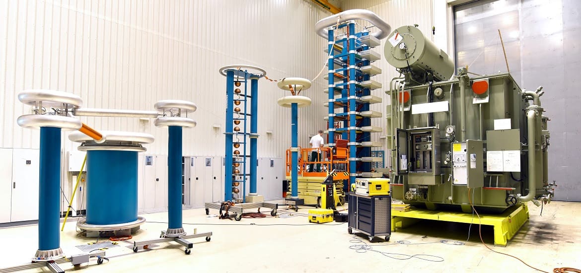
Figure 2 – Picture of power transformer during lab testing (click to zoom)
1.3 Factors Affecting Insulation Level Selection
When specifying insulation levels for a transformer, several factors must be considered:
1. System Voltage and Overvoltage Conditions: Higher voltage networks require stronger insulation to handle operational and transient stresses.
2. Location and Environmental Conditions: Transformers in lightning-prone areas may require a higher BIL to withstand frequent surges.
3. Neutral Grounding Configuration: Ungrounded or impedance-grounded systems may experience higher transient over voltages, requiring enhanced insulation levels.
4. Altitude Considerations: At altitudes above 1000m, air insulation strength decreases, requiring insulation corrections.
5. Load Characteristics and Harmonics: Transformers supplying non-linear loads (e.g., power electronics, HVDC systems) must handle additional dielectric stresses due to harmonic voltages.
Suggested Reading – Ground faults in ungrounded systems (risks & detection)
1.4 Importance of Proper Insulation Coordination
Insulation coordination ensures that a transformer can withstand system voltages, transients, and fault conditions while optimizing cost and performance. By selecting insulation levels based on IEC 60076-3 guidelines, engineers can:
- Minimize the risk of dielectric failures and insulation breakdowns.
- Optimize transformer design without excessive over-insulation, reducing costs.
- Ensure compatibility with system protection schemes and surge arresters.
Further Study – High voltage generation, overvoltages in power grids and insulation coordination
High voltage generation, overvoltages in power grids and insulation coordination
2. Short-Circuit Strength and Withstand Capability of Power Transformers
Power transformers are subject to high mechanical and electrical stresses during short-circuit conditions. A properly designed transformer must have sufficient short-circuit strength to withstand these forces without sustaining permanent damage.
IEC 60076-5 provides comprehensive guidelines for testing and verifying a transformer’s ability to endure short-circuit conditions, ensuring its reliability and durability in power networks.
2.1 Importance of Short-Circuit Strength
A short circuit occurs when an unintended low-impedance path forms between conductors, causing a sudden surge of fault current. These high-magnitude fault currents can reach values several times the rated current within milliseconds, subjecting the transformer to severe mechanical, electrical, and thermal stresses.
If a transformer lacks adequate short-circuit strength, it may suffer from:
- Winding displacement or deformation due to high electromagnetic forces.
- Internal insulation breakdown leading to dielectric failure.
- Damage to core clamping and structural components, affecting performance and lifespan.
Ensuring short-circuit strength is critical for system reliability, as transformer failures due to insufficient mechanical strength can lead to costly outages and equipment damage.
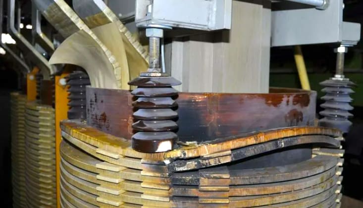
Figure 3 – Transformer winding damaged by short circuit tension
2.2 Types of Short-Circuit Stresses in Transformers
During a short circuit, a transformer experiences various stresses that impact its mechanical and electrical integrity:
1. Electrodynamic Forces on Windings: When large fault currents flow through transformer windings, they generate high radial and axial forces that try to compress or expand the windings. These forces can cause deformation, displacement, or even rupture of conductors.
2. Thermal Stress on Insulation: Fault currents generate rapid temperature rise, which can degrade insulation and lead to dielectric breakdown.
3. Mechanical Stress on Core and Clamping Structures: Short-circuit forces can cause loosening of core laminations, shifting of clamps, or displacement of bracing structures, affecting long-term transformer stability.
To ensure resilience against these stresses, transformers must be designed and tested to withstand fault currents without significant structural or electrical damage.
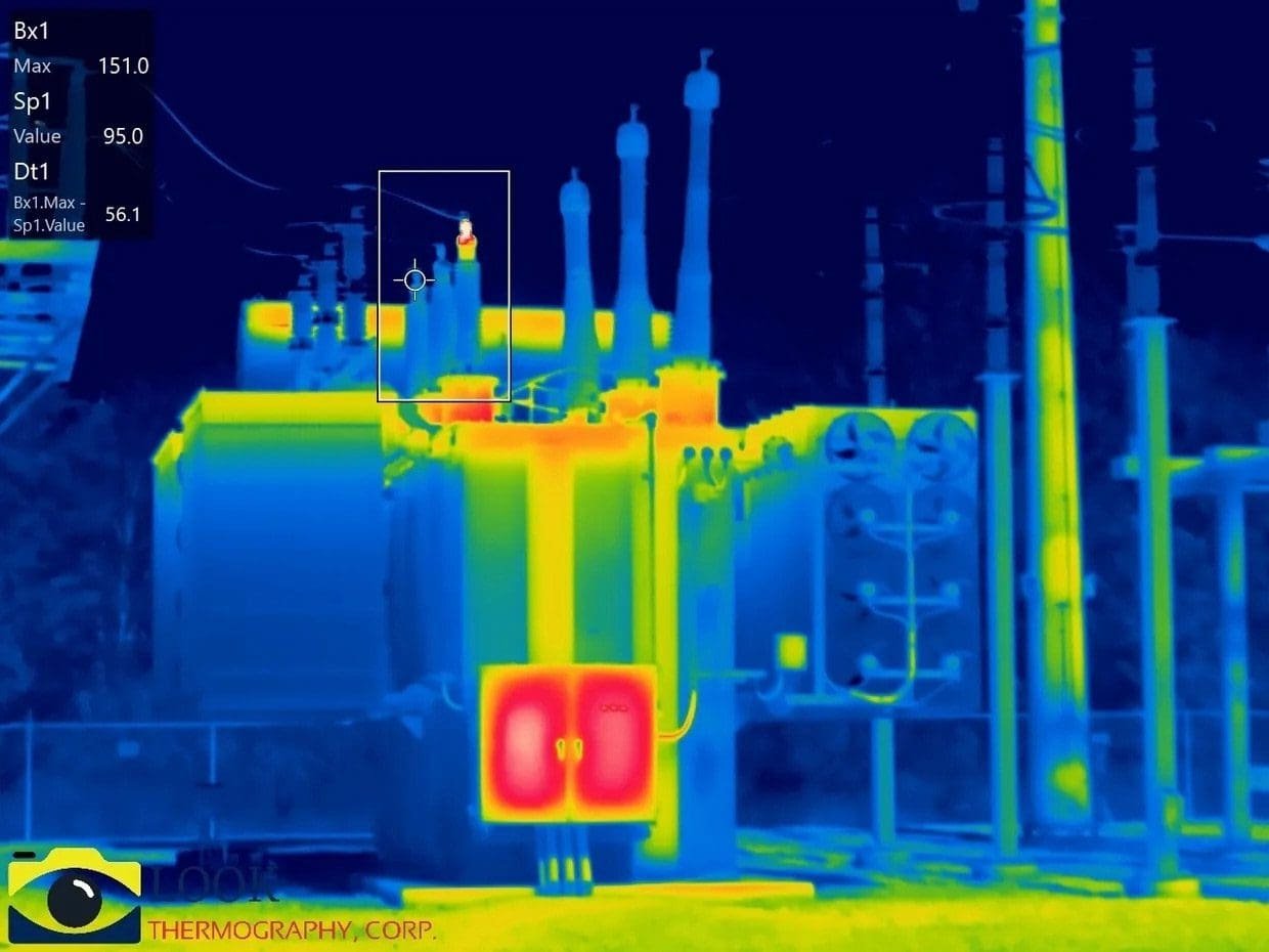
Figure 4 – Thermal infrared inspection of power transformer
2.3 Design Considerations for Short-Circuit Strength
IEC 60076-5 specifies that transformers should be designed to withstand short-circuit conditions through robust engineering practices, including:
1. High-Strength Conductors and Insulation: Windings must be constructed with mechanically strong conductors and adequate inter-turn insulation to resist deformation under high forces.
2. Reinforced Clamping and Bracing: The transformer core, windings, and structural components should be tightly clamped to prevent movement during a short circuit.
3. Optimized Winding Geometry: Using disc-type or interleaved winding arrangements helps distribute forces more evenly, reducing mechanical stress concentrations.
4. Controlled Short-Circuit Impedance: The impedance value must be carefully selected to limit fault currents, ensuring system stability while preventing excessive internal stresses.
5. Quality of Bushings and Leads: The external connections and bushings should be designed to handle high transient currents without flashover or mechanical failure.
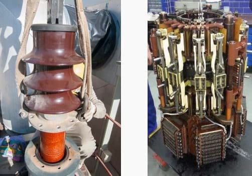
Figure 5 – Left: Damaged Bushing; Right: Faulty OLTC
2.4 Short-Circuit Withstand Testing (IEC 60076-5)
IEC 60076-5 mandates short-circuit withstand testing to verify that a transformer can handle fault currents without permanent damage. The standard defines two key tests:
a) Dielectric Short-Circuit Test
The Dielectric Short-Circuit Test is conducted to verify that the transformer’s insulation system can endure the short-duration over voltages that may occur during fault conditions. These transient over voltages can stress the insulation and potentially compromise the transformer’s reliability.
Related electrical guides & articles


Muhammad Kashif
Muhammad Kashif Shamshad is an Electrical Engineer and has more than 17 years of experience in operation & maintenance, erection, testing project management, consultancy, supervision, and commissioning of Power Plant, GIS, and AIS high voltage substations ranging up to 500 kV HVAC & ±660kV HVDC more than ten years experience is with Siemens Saudi Arabia.Profile: Muhammad Kashif
