
Estimated Study Time: 29 minutes
Introduction to Substation Automation System
Testing the protection element settings of IEDs and protection schemes are well established practices when testing a Protection, Automation and Control (PAC) system. Tools and methods are available to support standardized and automated protection testing routines. Test plans can be created for specific relay types and schemes to be reused during distinct phases of a project, like Factory Acceptance Tests (FAT), commissioning, Site Acceptance Tests (SAT) and maintenance.
 Testing the functional performance of a modern substation automation system with StationScout (photo credit: Omicron)
Contrary, testing the Substation Automation System (SAS), which involves many automation, control and SCADA functionalities, is usually performed manually. When looking at the time spent during commissioning, for example, testing the automation and communication system is currently more time consuming than testing the protection functions.
Automation systems have become increasingly complex and the efforts for testing communication, interlocking logic, and proper operation of all signals transmitted to SCADA systems have grown dramatically. In substations, all connection interfaces between IEDs and primary equipment need to be checked as part of the FAT and SAT. For hardwired interfaces, as an example, this is usually performed one-by-one in a manual process of “green marking” all interfaces on printed functional and wiring diagrams.
This process, which is preferably performed during FAT before delivery and installation at site, requires several weeks for a typical substation and involves several experienced control and SCADA engineers.
The following hardware, software and technical competencies shall be available for system testing in the factory:
- Ideally the entire SAS with all bay IEDs, networking equipment, gateways, HMIs, etc.,
- A switchgear simulator hardwired to the IEDs (can be simple switches and LED indicators up to sophisticated PLC based simulators),
- Control center simulator supporting the used SCADA protocol (e.g. IEC 60870-5-104, DNP3)
- Network testing tools and the IED specific maintenance tools
- Deep knowledge about the implemented vendor products, the IEC 61850 standard and Ethernet networks in general
- Well prepared test plans and documentation (Signal spreadsheet, interlocking logics and other test procedures)
Usually, not all components of the SAS are available at the factory, e.g. in cases where IEDs are part of switchgear deliveries and shipped directly to substation site without a proper system test done before. In such cases, testing must be exclusively performed on site, with consequences in terms of efforts and costs.
Practical experience shows that the better the system is tested in the factory, the less problems occur during installation and testing on site, and the more efficient and smooth the project finally is.
During the testing procedure, bugs and errors in device parameters but sometimes also in the device’ firmware are detected and fixed. But every update of firmware version and as well as any change of device settings requires at least retesting of the involved function, ideally a retest of the entire system. This process is not efficient if manual testing is performed, therefore a new approach towards more automated and efficient system testing is heavily needed.
Such a solution is available today and based on the SCL concept which is part of the IEC 61850 standard.
- IEC 61850 and the SCL Concept
- New SAS Testing approach based on SCD Files
- Practical Use Case: Extension of an existing substation
- Conclusion
1. IEC 61850 and the SCL Concept
IEC 61850, the international standard for Communication networks and systems for power utility automation, defines not just communication protocols, but also data models for substation equipment. Moreover, the standard also specifies a common, vendor independent configuration concept.
Machine readable configuration information in an XML based standardized format is used in this process – the System Configuration Language (SCL).
1.1 SCL Engineering Process
The SCL concept is defined in IEC 61850-6. Its main purpose is to allow the exchange of configuration data, in a compatible way, between different configuration and testing tools.
Figure 1 – SCL concept

Figure 1 shows the general concept of the engineering process of a substation automation system with the usage of SCL data exchange.
The following types of SCL files, with different extensions, are specified for exchange of information:
SSD (System Specification Description): describes the single line diagram of the substation, voltage levels, primary equipment and required logical nodes (LN) for implementing the substation automation functions. The SSD file is generated by a System Specification Tool (SST).
ICD (IED Capability Description): describes the functional capabilities of an IED type. Each IED type has its related ICD file. It contains the IED logical nodes, data and supported services. It is generated by the vendor specific IED Configuration Tool (ICT).
SCD (System Configuration Description): contains all configured IEDs, the communication configuration and all IEC 61850 aspects for a given system. It is created by the System Configuration Tool (SCT).
CID (Configured IED Description): contains a subset of the SCD file with all information related to one specific IED. Private extensions are allowed.
In principle, there are three types of engineering tools in this process: System Specification Tool (SST), System Configuration Tool (SCT) and IED Configuration Tool (ICT). Practically, an all-in-one tool and no SSD is often used in case in single-vendor systems. In multi-vendor installations with vendor specific ICTs, typically a dedicated SCT is used.
Today, more and more users understand the need for standardization and use an SST for the specification process.
By using data from the SSD file or by direct entry, the engineer can associate IED functions (Logical Nodes) to the single-line equipment and functions. Ultimately, the SCD file, documenting the complete system, is generated by the SCT.
1.2 SCL Content
The SCL language in its full scope allows to describe a model of the substation comprising of three basic parts:
Substation: describes the single line diagram of the substation, primary equipment and functions; The substation equipment such as a Circuit Breaker is “connected” to the virtual logical nodes contained in the IED;
IED: describes all the hardware devices (IEDs) used in the substation automation system. The data model implemented in the IED including its logical devices and logical nodes are described in this part. IEDs are connected to the communication system via its access-points;
Communication: describes logically possible connections between IEDs in sub-networks by means of access-points (communication ports).
Figure 2 – SCL content

The content of a complete SCD file is comprised of these three parts plus a section with data type templates describing which data and attributes are used by the IEDs.
1.3 Substation Structure and Functional Naming
The substation structure represents the primary system architecture and describes which primary equipment functions are used, and how the equipment is connected. The objects in this section are hierarchically structured and designated according to IEC 81346.
Figure 3 shows an example of a substation single line diagram following the naming conventions of IEC 81346 for the substation structure and equipment such as disconnect switches and breakers.
Figure 3 – Example substation topology
The main purpose of this section is to derive a clear functional designation for the abstract logical nodes, which are implemented in the IEDs to the primary equipment in the substation. Otherwise it might be difficult for the system tester to find out which specific LN-instance in the IED is “connected” to which primary element in the switchgear.
1.4 Content and Usage of SCD Files
As explained above, the SCD file is the ultimate file resulting from a completed IEC 61850 system design. The SCD file is not only used by engineering tools and for documentation purposes, but also by testing tools. Testing tools can support a more efficient testing, taking advantage of the SCD file information about the substation under test.
However, while the standard defines a clear concept for the engineering process, it does not define a minimum content requirement for the SCD file. Topology information in the substation section, for example, is optional. Information in the IED section depends on the capabilities of the specific IED products used in the project.
So, it is strongly recommended for asset owners to include minimum requirements on the SCD file into SAS specifications used for project tenders and service contracts, such as:
- Substation section must contain all voltage levels, bays and CBs/disconnectors with their LN references (XCBR/XSWI, CSWI and CILO)
- Data Objects include “desc” description attributes with signal text as defined by the owner,
- GOOSE subscriptions use <IEDName> elements in the element, and use <Inputs><ExtRef type=”GOOSE”> elements
- RTUs/Gateways or HMIs must be defined, have the Report Control Blocks in the IED reserved and declared using <ClientLN> in the <ReportControl> element.
- All data sets used in report reports are of static type (as dynamic data sets are not documented in the SCD)
The better the quality and content of the substation’s SCD file, the higher the efficiency of system testing will be. A compliant SCD file is also highly supporting later extensions of the station as described later.
2. New SAS Testing approach based on SCD Files
2.1 Test Approach
As mentioned, testing of the automation and control functionality are usually performed in a manual way. Since many years, tools are available offering testing capabilities on a per IED basis, allowing manual test and simulation of individual IEDs.
As can be seen in Figure 5, the tester gets to view the system in a very similar way as the single-line diagram or the local substation HMI, which he is already familiar with.
The method proposed is suitable for testing the SAS during its entire project lifecycle, which project phases are described at IEC 61850-4 and illustrated in Figure 4.
The tool using this method should support both monitoring as well as simulation of the system. When testing, the test set should have access to the GOOSE network traffic and a MMS connection to the IEDs.
Figure 4 – SAS lifecycle

During specification phase, the SCD file, the signals and communication services can be validated without need of any physical device. Later, testing of SCADA gateways and HMIs can be performed by simulating the communication behavior and signals of all IEDs – again without any real IED. During the FAT, IEDs that are not yet present can be simulated to test those ones which are already available.
As the project moves into the commissioning stage, more monitoring and testing of the real IEDs is done instead of simulation.
One of the key factors for an efficient approach is the option to create test plans. A test procedure can be documented and reused throughout the SAS lifecycle. Test sequences can be performed and assessed automatically.
2.2 SAS Functional Testing with StationScout
StationScout is the innovative testing solution for IEC 61850 substations which provides the required testing features as described before. StationScout simplifies testing for the SAS and significantly reduces the required testing effort. It comes with a robust and powerful hardware that allows users to simulate multiple IEDs with a secure isolation to the SAS networks.
This user-friendly software helps to visualize SCL files or tracing signals within the substation without any configuration effort.
Figure 5 – Example SCL loaded into StationScout

Some practical use cases of StationScout related to troubleshooting and testing of SAS are discussed in the following sections.
2.3 Verification of Communication Links
By loading the SCD file and having access to the network traffic and MMS connection to the IEDs, StationScout can automatically validate all GOOSE, Sampled Values and Report communication links. The test set can poll for attributes in the IEDs and validate against the model. The user can check, for example, if the Report Control Blocks are currently enabled and if the Owners of the Reports are the Clients declared in the SCD file.
GOOSE communication links will be automatically verified for:
- GOOSE mismatch on the sender side: by verifying Control Block settings;
- GOOSE publishing errors: by sniffing on the network and comparing against SCD;
- GOOSE subscription errors: by verifying the LGOS statuses at each subscribing IED. Mismatches are also checked.
Figure 6 illustrates an example where the GOOSE published by an IED is verified in the network, but StationScout identifies a problem at one of the subscribers due to a mismatch in the configuration revision. The connection link is highlighted in yellow and warning signs are displayed to indicate the issue.
Figure 6 – Check of GOOSE Publisher-Subscriber links

2.4 Testing Interlocking Logics
PLC Logic is implemented in most IEDs to cover control and automation functions. They can be automatically tested by simulation of the inputs of the logic (either via IED simulation or real switchgear status) and assessment of the results of the logic calculations with StationScout. One application example is the use of logics for interlocking schemes to ensure proper operation of disconnect and grounding switches.
To represent the result of interlocking logic conditions, IEC 61850 defines the status of the release in the logical node CILO. For testing, a subset or ideally all possible combinations of inputs can be tested, and the logic output assessed by automatically reading the CILO status values.
Figure 7 – Testing of interlocking schemes: Interlocking logics and definition of test steps in spreadsheet

Figure 8 – Results of interlocking test after execution with StationScout

2.5 Troubleshooting by Tracing Signals
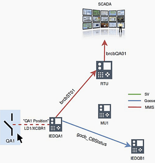
There are multiple transfers of messages and signals within a SAS system. A signal passes multiple steps until it arrives at the control center. If there is an error in this communication, the commissioning engineer needs to follow the signal on its way through the SAS. Finding such signal errors can be very time consuming.
Using StationScout it is possible to follow how the signals propagate through the SAS.
Figure 9 – Breaker position transmitted over the SAS
2.6 Testing RTU/Gateway and local HMI Configuration
Gateways, RTUs and local HMIs usually communicate with almost all IEDs in the system, mainly via Reports, but also GOOSE. Typically, several thousand of signals need to be tested per substation. During commissioning, at least the most critical signals are tested point-to-point by stimulating the signal in the switchyard. All other signals can be simulated by StationScout.
A test plan can be built with StationScout simulating all IEDs and signals of the substation for a quick verification if the RTU and gateways are correctly configured.
Those tests can be performed in the substation with all other IEDs simulated by StationScout without affecting the devices in operation.
3. Practical Use Case: Extension of an existing substation
For an important 20kV Indoor Substation with around 55 IEDs, 3 busbars and two bus sections in a large industrial complex, the owner decided to extend the existing substation with several additional bays. The substation was commissioned around 10 years ago with a modern PAC system based on IEC 61850. Due to the operational constraints, the extension must be performed without de-energizing and during operation of the substation.
To realize this, the bay devices send their switch positions and other information via GOOSE to the interlocking IED, which calculates topological information such as “busbar 1 grounded” and sends this information again via GOOSE back to the bay devices, where the final command releases are calculated. Benefit: If the central device fails, the bay-related interlocks remain available.
And most important: Existing bay IEDs are not affected in case of extensions of the substation!
Figure 10 – Principle system diagram of the SAS (grey… scope of extension project)

This way of implementation allows subsequent extension without retesting the existing bays and – when using modern testing tools like StationScout – also during operation.
3.1 Factory testing of the new IEDs
As the majority of the IEDs are already in operation, the IEDs for the new bays could not be factory tested together with the existing IEDs and station level devices. Therefore, the owner decided to perform the test of the new IEDs with a spare Interlocking IED and the rest of the substation to be simulated by StationScout (Figure 11).
At first, the engineer imported the existing SCD file into a new project data base, added the new IEDs, updated the central interlocking IED, the HMI and the gateways in order to incorporate the new bays and finally created a new SCD file of the entire substation (existing + extension).
The existing bay control and protection IEDs remained unaffected and will not be loaded with new parameter files.
Figure 11 – Test setup of the new IEDs in the factory

For each disconnector’s open/close operation in the new bays, test cases with >50 test steps have been defined as a permutation table in a spread sheet (Figure 7) and implemented in StationScout. The test cases have been created just once for a typical bay and easily copied for the others. Finally, those test steps have been executed by simulation of the existing IEDs and assessment of the relevant CILO data objects in the new IEDs (Figure 11).
This way, the correct implementation of the interlocking scheme in the central interlocking IED as well as in the new bay IEDs has been verified.
3.2 Testing of the updated gateways
A second part of the extension project involves the update of the existing gateways with latest CPU hardware and firmware for cybersecurity reasons. Considering the extensive evolution of hardware and firmware during the past 10 years, a complete retest of around 2.000 signals from the IEDs to the Control Center after the update was highly recommended.
As the station is equipped with redundant gateways, one of the two gateways can be disconnected from the Station LAN without disturbing remote control from the control center. Each gateway will be upgraded, and a complete signal test will be performed by simulating all reports and SCADA signals with StationScout, verifying the correct function of the gateway up to the control center.
4. Conclusion
An innovative test approach was presented for testing the communication, automation, control and SCADA part of the SAS system, which is based on the SCD file information. Test plans can now be created to automate the test and document procedures that have been very time consuming until now.
Automated test plans also enable a quick re-test after security patches and firmware updates, which are performed quite often nowadays. Testing is becoming an integral part of the system and quickly evolving into a supervision and monitoring role.
About Authors
![]()
Christian Brauner
OMICRON electronics GmbH, Austria
![]()
Eugenio Carvalheira
OMICRON electronics Corp., USA
Related electrical guides & articles


Christian B. and Eugenio C. at OMICRON
Christian Brauner - sales development manager. His special focus is on testing and monitoring solutions for substation automation systems; Eugenio Carvalheira - has over 18 years of experience in the design and commissioning of power systems protection, automation and control systems.Profile: Christian B. and Eugenio C. at OMICRON

Thanks for this interesting article, I am an electrical protection and control engineer, from Egypt. Could you please let me know more about Substation Automation Testing Techniques and GOOSE Communication.
Thank you for taking your time to read our article. Please provide us with your email address so that we can send you more information on Goose communication. We look forward to hearing from you.
Thank you for the article. I am electrical maintenance engineer from M/s NTPC Ltd, India. Kindly send more information about goose communication.
Hello Sumit,
Thank you for your interest in our article. If you provide us with your email, we can send you the goose information.
Best Regards,
Thank you for the article. Nice. Electrical Engineer in the area of Automation, Control and protection. Please send more information or any updates in the future.
Thank you for your article. I am Lead Electrical Engineer for Jawa Satu Power 1760 MW CCPP Project, Indonesia. Kindly send more information about goose communication. And hope EEP will available to provide online distance training .
I am very Interested about ( https://electrical-engineering-portal.com/functional-testing-iec-61850-based-substation-automation-systems ).
Thank you very much & Best Regards
thanks for sharing the information, it would be very helpful to me if you could write more about goose communication.