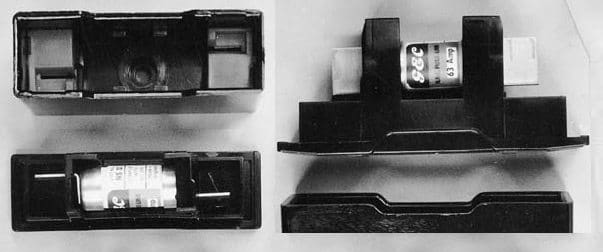
 A fuse consists of a replaceable part (the fuselink) and a fuse holder. Examples of fuse holders are shown in Fig. 1. The simplest fuselink is a length of wire. It is mounted by screw connections in a holder which partly encloses it. When an overcurrent or short-circuit current flows, the wire starts to melt and arcing commences at various positions along it. The arc voltage causes the current to fall and once it has fallen to zero, the arcs are extinguished.
The larger the wire cross section, the larger is the current that the fuselink will carry without operating. In the UK, fuses of this type are specified for use at voltages up to 250 V and currents up to 100 A. They are known as semi-enclosed or rewireable fuses.
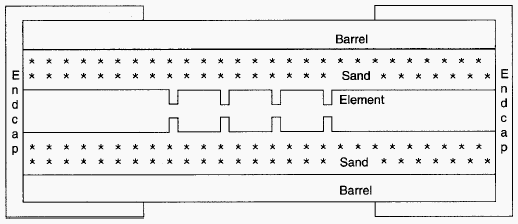
The most common fuselink is the cartridge type. This consists of a barrel (usually of ceramic) containing one or more elements which are connected at each end to caps fitted over the ends of the barrel. The arrangement is shown in Figs 2 and 3. If a high current breaking capacity is required, the cartridge is filled with sand of high chemical purity and controlled grain size. The entire fuselink is replaced after the fuse has operated and a fault has been disconnected. Cartridge fuses are used for a much wider range of voltages and currents than semi-enclosed fuses.
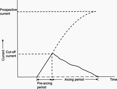
Fuselinks can be divided into current-limiting and non-current-limiting types. A sand-filled cartridge fuselink is of the current-limiting type; when it operates, it limits the peak current to a value which is substantially lower than the prospective current. A non-current-limiting fuse, such as a semi-enclosed fuse, does not limit the current significantly. The element shown in Fig. 2 is a notched tape. Melting occurs first at the notches when an overcurrent flows and this results in a number of controlled arcs in series. The voltage across each arc contributes to the total voltage across the fuse, and this total voltage results in the current falling to zero. Because the number of arcs is limited, the fuselink voltage should not be high enough to cause damage elsewhere in the circuit.
The characteristic development of current and voltage during the operation of a fuse is shown in Fig. 8.6. The function of the sand is to absorb energy from the arcs and to assist in quenching them; when a high current is disconnected, the sand around the arcs is melted.
Fig. 1 Fuse holders for miniature and compact LV fuses


The element is usually of silver because of its resistance to oxidation. Oxidation of the element in service would affect the current that could be carried without melting, because the effective cross section of the element is changed. Silver plated copper elements are also used.
Many elements include an m-effect blob, which can be deposited on wire (Fig. 1 b) or notched tape. The blob is of solder-type alloy which has a much lower melting point than the element. If a current flows which is large enough to melt only the m-effect blob, the solder diffuses into the silver. This creates a higher local resistance in the element and the fuse operates at a lower current than it would have done in the absence of the blob.
Other types include the expulsion fuse which is used at high voltage, and the universal modular fuse (UMF) which is used on Printed Circuit Boards (PCBs). Fuses offer long life without deterioration in their characteristics or performance, and cartridge fuses have the particular advantage that they contain the arc products completely.


Please help mathematical model for fuse designing
Why arcing period time longer than pre_arcing period?
Very informative and useful post, both for students and engineering professionals. Highly recommended.
i read the article its very knowledgeable and its good for the enginneering students and proffessionals