
The fuse. Simple and reliable.
Fuses are the oldest and simplest methods of protecting rural networks. There is no method as simple as fuses, but don’t be tricked, modern fuses are very reliable devices. All they need is a good discrimination achieved to be almost completely reliable.
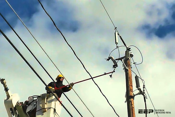 Fuses as the oldest and simplest method of protecting rural distribution systems
Two types of high-voltage fuse are now generally available for the protection of rural systems, namely:
- Expulsion type
- Current limiting (powder filled high breaking capacity) type.
The liquid filled fuse was once widely used but troubles were experienced due to breakage of the glass and leakage of liquid. Furthermore, its application was somewhat restricted by its limited breaking capacity as system fault levels increased.
The expulsion type is cheaper in capital cost and fuselink replacement and with available ratings being suitable for the fault power levels normally encountered in rural networks, its use has now superseded that of the liquid tidied fuse.
For fault levels in excess of 150 MVA at 11 kV, an adaptation of the expulsion fuse carrier to incorporate a cartridge type powder-filled fuse link may be employed.
The construction of the expulsion type fuse readily permits the removal of the fuse link to be used as a means of isolating the protected equipment.
As won’t get much into the construction of these two fuse types, we will focus this discussion on their protection application in rural power networks.
Application of fuses
Early applications tended to fuse each spur line and individual transformer separately, as in Figure 1, the fuse rating being related to the full load current rating of the plant protected.
Whilst fuse blowing due to transformer failure was infrequent, surges during lightning storms often resulted in widespread fuse operation without permanent damage to apparatus.
This led to the concept of ‘group fusing’, that is the protection of a number of transformers on a spur line by a single set of fuses at the spur tapping point, as shown in Figure 2.
This safeguards the main line from disturbances on the spur and is the principle generally employed today.
This, however, has the disadvantage that low current faults, such as transformer interturn failures and certain broken conductor faults, may not cause the fuse to operate.
The number of such incidents is, however, negligible in comparison with those caused by lightning and, with the high reliability of modern distribution transformers and present day overhead line design, the principle of HV group fusing is undoubtedly justified.
Overload protection of individual transformers is provided by LV fuses.
Current flowing to a fault on the LV side of a transformer is supplied via the HV group fuse and, under these conditions, the LV fuse protecting the faulty circuit should operate first in order that the HV supply to healthy transformers is not affected.
This is shown in Figure 3 where the HV and LV fuse protection of three-phase 11/0.44 kV transformers is illustrated.
A 100 kVA transformer having an impedance of 4.75 per cent and connected to an HV system having a fault level of 150 MVA will pass a maximum LV fault current of 2760 A.
For all values of fault current up to this figure discrimination will be obtained between the HV expulsion type fuse of 25 A rating and the high breaking capacity LV fuse of 300 A rating, tolerances on fuse characteristics being neglected.
The ratio between LV and HV fuse ratings is 12:1, although the transformation ratio is approximately 25:1, discrimination with fuse ratings of this ratio being made possible by the high speed of the filled type of fuse relative to that of the expulsion type.
An LV fuse of 400 A rating will not discriminate with the 25 A HV fuse at fault currents below the maximum that can occur on the LV side of the 100 kVA transformer but will do so at higher values of fault current which may be experienced oll the LV side of larger transformers.
In the case of transformer HV and LV fuses, the current values must be converted to a common voltage base.
Discrimination will result if the characteristics are separated by an interval of at least the sum of the permitted characteristic tolerances for the fuses in question.
Figure 4 shows the discrimination limits for three commonly used sizes of expulsion fuse. The lines AA represent for each rating the published characteristic whilst the lines BB have been plotted with the current ordinates reduced to 0.75 of the values represented by AA. These fuses will discriminate since the shaded area between the lines for any rating does not overlap that of the other ratings.
In some instances, the use of fuse links with a slower operating characteristic at the higher currents may be required to obtain adequate discrimination. Fuse links with such characteristics are available in the liquid filled and expulsion types but are not available with the powder-filled high breaking current fuse – HBC (or high rapture current – HRC), type which is inherently fast in operation.
A comparison of tile relative pre-arcing times of fast and slow blowing HV fuse links is illustrated in Figure 5.
Some types of fault on the low-voltage side of transformers employing certain winding connections will give rise to unbalanced currents on the high voltage side and currents in excess of those carried by a balanced three-phase fault may occur.
It is essential therefore to ensure that adequate discrimination can be obtained with these particular fault conditions.
Experience has indicated that the time/current characteristics of overhead line HV fuses change after a length of time in service and mal-discrimination may occur between fuses in series, even though correct discrimination is indicated by a comparison of their published characteristics.
For this reason and because of the wide tolerances on the characteristics sometimes encountered, the use of such fuses in series is not recommended.
Source: Power system protection by The Institution of Electrical Engineers


Very Educative and I’m your student especially in High Voltage thanks and be blessed.