
Introduction to Powerhouse
In general, a powerhouse in hydropower plant may be divided into three areas:
- The main powerhouse structure, housing the generating units and having either separate or combined generator and turbine room,
- Erection bay, and
- Service areas.
1. Main powerhouse structure
The generator room is the main feature of the powerhouse about which other areas are grouped.
It is divided into bays or blocks with one generating unit normally located in each block. The width (upstream-downstream dimensions) of the generator room for the indoor type should provide for a passageway or aisle with a minimum width of 10 feet between the generators and one powerhouse wall.

The height of the generator room is governed by the maximum clearance height required for dismantling and/or moving major items of equipment, such as parts of generators and turbines; location of the crane rails due to erection bay requirements; the crane clearance requirements; and the type of roof framing.
The elevation of the turbine room floor should be established so as to provide a minimum requirement of 3 feet of concrete over a steel spiral case, or a minimum roof thickness of 4 feet for a semispiral concrete case.
In establishing the distance between the generator and turbine room floors, if they are not combined, the size of equipment to be handled in the turbine room, the head room between platforms in the turbine pit, and the generator room floor construction should be considered.
2. Erection bay
In general, the erection bay should be located at the end of the generator room, preferably at the same floor elevation and with a length equal to at least one generator bay.
However, no additional space should be required if the access railroad enters from the end of the powerhouse.

In cases where the elevation of the crane rail would be dependent on the requirement that a transformer with bushings in place be brought under the crane girder, consideration should be given to the possible advantages of revising the layout to permit bringing the transformer in at the end of the structure, at the end of the generator room, if the generator room is at a lower elevation than the erection bay, or removing bushings before moving transformer into powerhouse.
3. Service area
Service areas include: offices, control and testing rooms, storage rooms, maintenance shop, auxiliary equipment rooms, and other rooms for special uses.
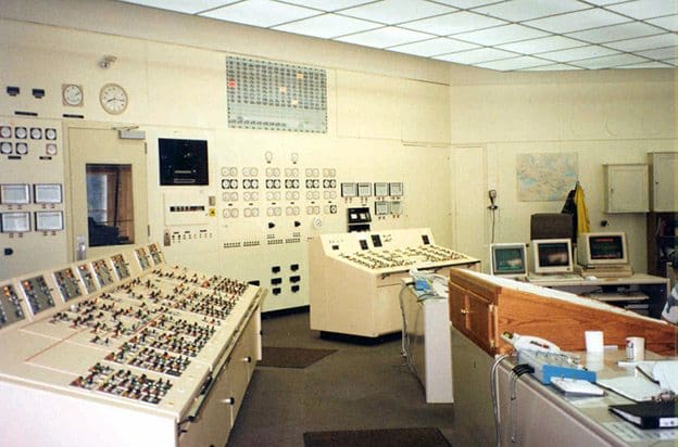
For plants located at the toes of gravity dams, the space available between the generator room and the face of the dam is a logical location for most of the features enumerated above.
However, in all cases an economic study, which should include the cost of any added length of penstock required, should be made before deciding to increase the space between the dam and powerhouse to accommodate these features. The offices are frequently located on upper floors, and the control room and other service rooms on lower floors.
The most advantageous location for the maintenance shop is usually at the generator room floor level.
Space allocations
Space should be provided for some or all of the following features and uses, as required:
1. Public areas: main public entrance, reception area, public rest rooms, exhibits, and elevator.
2. Employee areas: employee entrance, equipment entrance, offices, office storage, rest rooms for office use, control room, rest rooms for control room operators, kitchen for control room operators, repair and test room for instruments, main generator rooms, main turbine rooms, station service or fish water units area, erection and/or service areas.
3. Shops: machine, electrical, electronic, pipe, welding, sheet metal, carpenter, and paint with spray booth.
4. Storage and miscellaneous areas: storage battery and battery charger rooms, cable galleries, cable spreading room under control room, telephone and carrier current equipment room, oil storage tank room, oil purification room, storage for paints and miscellaneous lubricants, storage rooms, locker rooms with showers and toilet facilities, first aid room, lunch room with kitchen facilities, elevator, heating, ventilation, and air conditioning equipment rooms, and auxiliary equipment rooms.
Reference: Planning and Design of Hydro-Electric Power Plants – Gilbert Gedeon, P.E.; Continuing Education and Development, Inc.





My addressees, Assalamu Alaikum, Rahmatullahi wa Barakatuh.
No event is accidental, our relationship is also a planned opportunity.
Assalamu Alaikum to your esteemed position.
I am happy to be in touch with you and believe that our relationship can have positive achievements beyond our imagination.
Our company has recently reached a mutual understanding with the authorities of the Afghanistan State Electricity Company and foreign institutions working in the field of water energy utilization that all water energy related works in Afghanistan (rehabilitation of poorly implemented systems and selection of new projects, survey, design and implementation) will be carried out through our company.
Our company is committed to conducting accurate surveys of the areas, obtaining accurate information on the amount and height of water, and completing all the works on site until installation.
Our company wants to have a good and honest partner, although our project is small but it is very big and very interesting.
I hope you can give advice and encouragement in this regard.
Ziauddin Zeb
At What depth is the turbine and generator located in relation to dam level .
What is the nominal water pressure required at turbine nozzle for a 50 meter high dam ?
Is the pen stock (the tunnel that convey water from dam to turbine) further down from dam bottom ? If so how much ?
Wish to know the nominal head pressure at turbine for a dam of 50 meter high
Well, these are a layman’s questions.
Sorry about asking dumb questions
remarkable! thank you so much. I need much on optimization methods using programming. if you don’t mind, i will ask.
I am truly impressed with your knowledge and I may need you in future for a hydro electricity plant.
Thank you for the excellent knowledge base you have posted.
Very interesting and valuable site for EE I love it!!!!
Interested potential customer.