
Estimated Study Time: 7 minutes
Transmission of electricity
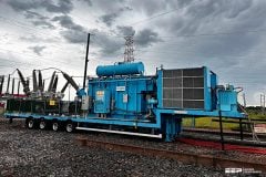
The generation of electricity in most modern power stations is at 25 kV, and this voltage is then transformed to 400 kV for transmission. Virtually all the generators of electricity throughout the world are three-phase synchronous generators.
The generator consists of a prime mover and a magnetic field excitor. The magnetic field is produced electrically by passing a direct current (d.c.) through a winding on an iron core, which rotates inside three-phase windings on the stator of the machine. The magnetic field is rotated by means of a prime mover which may be a steam turbine, water turbine, gas turbine or wind turbine.
A 2000 MW station might contain four 500 MW sets, three 660 MW sets and a 20 MW gas turbine generator or two 1000 MW sets.
Having a number of generator sets in a single power station provides the flexibility required for seasonal variations in the load and for maintenance of equipment. When generators are connected to a single system they must rotate at exactly the same speed, hence the term synchronous generator.

Very high voltages are used for transmission systems because, as a general principle, the higher the voltage the cheaper is the supply.
Since power in an a.c. system is expressed as P = V Icos θ, it follows that an increase in voltage will reduce the current for a given amount of power. A lower current will result in reduced cable and switchgear size and the line power losses, given by the equation P = I2R, will also be reduced.
The 132 kV grid and 400 kV supergrid transmission lines are, for the most part, steel-cored aluminium conductors suspended on steel lattice towers, since this is about 16 times cheaper than the equivalent underground cable.
Figure 1 shows a suspension tower on the National Grid network.

The conductors are attached to porcelain insulator strings which are fixed to the cross-members of the tower as shown in Figure 2. Three conductors comprise a single circuit of a three-phase system so that towers with six arms carry two separate circuits.
Primary distribution to consumers is from 11 kV substations, which for the most part are fed from 33 kV substations, but direct transformation between 132 and 11 kV is becoming common policy in city areas where over 100 MW can be economically distributed at 11 kV from one site.
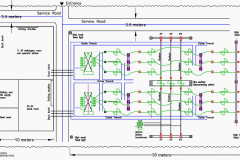
Figure 3 shows a block diagram indicating the voltages at the various stages of the transmission and distribution system and Figure 4 below shows a simplified diagram of the transmission and distribution of electricity to the consumer.

The maintenance of a secure supply is an important consideration for any electrical engineer or supply authority because electricity plays a vital part in an industrial society, and a loss of supply may cause inconvenience, financial loss or danger to the consumer or the public.
The principle employed with a ring system is that any consumer’s substation is fed from two directions, and by carefully grading the overload and cable protection equipment a fault can be disconnected without loss of supply to other consumers.

High voltage distribution
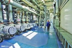
High voltage distribution to primary substations is used by the electricity boards to supply small industrial, commercial and domestic consumers.
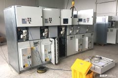
This distribution method is also suitable for large industrial consumers where 11 kV substations, as shown in Figure 5 may be strategically placed at load centres around the factory site.
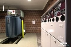
Regulation 9 of the Electricity Supply Regulations and Regulation 31 of the Factories Act require that these substations be protected by 2.44 m high fences or enclosed in some other way so that no unauthorized person may gain access to the potentially dangerous equipment required for 11 kV distribution. In towns and cities the substation equipment is usually enclosed in a brick building, as shown in Figure 6 .
The final connections to plant, distribution boards, commercial or domestic loads are usually by simple underground radial feeders at 400 V/230 V.

These outgoing circuits are usually protected by circuit breakers in a distribution board.
The 400 V/230 V is derived from the 11 kV/400 V sub-station transformer by connecting the secondary winding in star as shown in Figure 7 .
The star point is earthed to an earth electrode sunk into the ground below the substation, and from this point is taken the fourth conductor, the neutral. Loads connected between phases are fed at 400 V, and those fed between one phase and neutral at 230 V.

A three-phase 400 V supply is used for supplying small industrial and commercial loads such as garages, schools and blocks of flats. A single-phase 230 V supply is usually provided for individual domestic consumers.
Reference: Advanced Electrical Installation Work – TREVOR LINSLEY Senior Lecturer Blackpool and The Fylde College (Get this excellent guide from Amazon)
Related electrical guides & articles


Edvard Csanyi
Hi, I'm an electrical engineer, programmer and founder of EEP - Electrical Engineering Portal. I worked twelve years at Schneider Electric in the position of technical support for low- and medium-voltage projects and the design of busbar trunking systems.I'm highly specialized in the design of LV/MV switchgear and low-voltage, high-power busbar trunking (<6300A) in substations, commercial buildings and industry facilities. I'm also a professional in AutoCAD programming.
Profile: Edvard Csanyi

We were browsing for possible outsourcing for our Family Alternative Energy venture to cover mostly untapped, underdeveloped Philippines’ remote island cities, hoping to utilize our proprietary unheard-of Perpetual Motion Machine.
Smooth!
great article …thanks
In our plant the highest transmission voltage is 765kV.
nice artical, thanks
nice explanation but we are using transformers according our needs I thing after the power plant it should have a transformer to obtain transmission lines 400kv or 275kv or 132kv but for the rest everything is perfect
brief and precise
A brief extraordinary description of power grid
such a brief and excellent explanation about electrical power system.
yes you have written perfectly about power supply.